This thread has been locked.

If you have a related question, please click the "Ask a related question" button in the top right corner. The newly created question will be automatically linked to this question.

TDC1000: About the sensor interface circuit for ΔTOF drift improve

Part Number: TDC1000
Other Parts Discussed in Thread: MSP430FR6043,

Dear Sirs,

My customer has some question about the sensor interface circuit in SNIA020.pdf application document.

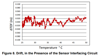
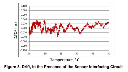
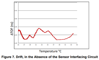
In the file, the ΔTOF drift cane be improve with sensor interface circuit of TDC1000.

My customer is interested in it and asks if there is any detailed information on how to implement it?

Thanks.
   

  • Hello Peter,

    Thanks for posting to the sensing forum! I wanted to first mention that TDC1000 is not our recommended device for flow metering due to its low accuracy, the recommended solution for high accuracy flow metering is the MSP430FR6043 which they  can look at here: https://www.ti.com/product/MSP430FR6043

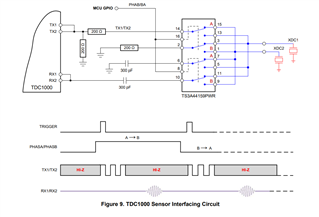
    Regarding the sensor interfacing circuit, is a simple impedance matching circuit that is used to better match the performance of the two transducers drift behavior over temperature. This helps reduce the resonance frequency shift as well as the improved amplitude matching between the two transducers. If the two transducers that the customer is using are already matched then they might not see a huge improvement in their performance. The circuit is shown in figure 9 of the app note mentioned, I have included an image of the circuit below:

    There is a bit more info in section 2.4 of this document: Analog Electronics Design to Improve Performance of Ultrasonic Gas Flow Meter. There is also additional references at the end of this document that the customer might be able to reference if they need additional resources. Other than that we do not have a dedicated document on how to implement this circuit, I hope this helps!

    Best,

    Isaac

  • Hi Isaac,

    Thanks for your explanation!

    May I have another question that how to choose the R and C value of this circuit?

    Is there any formula available?

    Thanks.

  • Hello Peter,

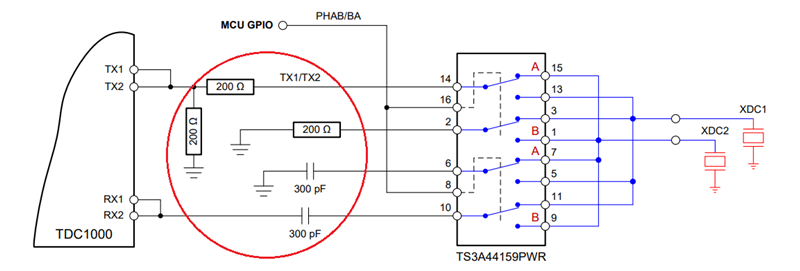
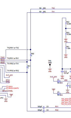
    The C capacitor value of 300pF is the suggested value when using the device is capacitive feedback, so this value does not have to be calculated (see figure below).

    The only values that need to be tuned are the R values in the circuit. Unfortunately, I do not have a formula on how to tune this value. As mentioned it is used to improve the amplitude and frequency shift over temperature. The customer might need to monitor these parameters on the transducer in order to find the ideal R values to use.

    Best,

    Isaac

  • Hi Isaac,

    Other questions:

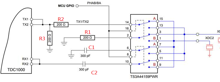
    1. About R1, R2, and R3, which one is necessary to lower the drift?

    2. Why need to add C1 for sensor TX?

    Thanks.

  • Hello Peter,

    I have not tested this circuit myself so here are some thoughts on it:

    1. I believe all resistors are needed in order to reduce drift. R2 is already present on the TX path of the TDC1000-C2000EVM (see schematic below) with the addition of R3 it allows you to create a divider network to tune the amplitude of the driving voltage. Since R2 and R3 handle the TX path,  R1 will handle the impedance on the transducer connected to the RX path. This keeps all transducers connected to the a resistor during upstream or downstream flow.

    2. I am not sure if the C1 capacitor is needed for the TX, this may have been carried over from the TDC1000-C2000EVM (see schematic below) since there is a 300pF capacitor connected at all times in the TX path due to the RX path being connected at all times in the EVM. It does not seem to serve much of a purpose to me in this circuit unless if contributes to the impedance matching of the transducer.

    Best,

    Isaac