This thread has been locked.

If you have a related question, please click the "Ask a related question" button in the top right corner. The newly created question will be automatically linked to this question.

TMAG5170-Q1: TMAG5170 Data frame Status Bit information

Part Number: TMAG5170-Q1

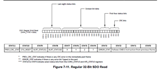
From the datasheet, figure 7-11 overviews the return data status registers. "Stat10-4 are select status bits from the CON_STATUS and AFE_STATUS registers"...

Is ALRT_STATUS1/0 = ALRT_STATUS from the CONV_STATUS register?

What are "X" to "T" status bits? Are those TEMP_STAT ... XHS_STAT bits from AFE_STATUS? Are those T ... X bits from the CON_STATUS register? 

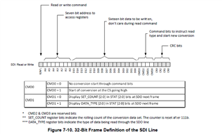
What does "CMD0 = 0, No conversion start through command bits" mean? Does that mean that sending a write command does not trigger a conversion? 

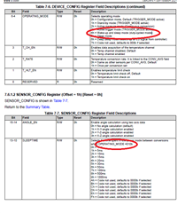
What does "CMD1 =1, Start of Conversion at the CS going high" mean? Does that mean that at the end of an SPI communication operation, a conversion is triggered? 

  • Chad,

    thanks for reaching out on E2E.  

    1. You are correct. The ALRT_STATUS 1/0 bits should correlate with ALRT_STATUS in the CONV_STATUS register.

    2. The X,Y,Z,and T status bits should correspond to bits [8:11] of the CONV_STATUS register which indicate whether the data is current.  The XHS_STAT (or Y or Z) are diagnostic outputs which indicate whether any internal errors are detected in the function of the Hall-effect sensor. TEMP_STAT runs a somewhat different diagnostic on the temperature sensor and provides feedback on device function.

    3. CMD0 is tied to the SPI command trigger option.  When TRIGGER_MODE = 0, sending CMD0=1 will initiate a conversion at the end of that SPI transmission (when CS is returned HI). Sending CMD0=0 will not trigger a conversion.  This might be desired to prevent the device from running conversions during device initialization, or for reading status of other registers like Temperature. 

      If TRIGGER_MODE = 1, then conversions may be started by the falling edge on CS.  This means that CS may be used as a trigger without requiring a complete SPI transaction.

    Thanks,

    Scott

  • Hi, 

       thank you for your response. Additional question, Sleeptime impacts the Wakeup and Sleep mode operating mode 0x4, not 0x2 right? 

  • Chad,

    Yes.  The setting on sleep time will dictate how long the device remains in sleep during the wake and sleep mode.

    Thanks,

    Scott

  • Hi Scott, 

       For 1mS Wake-Sleep cycling, does the data rate meaningfully differ from 1kSPS? I'm testing the device, pinging it for data in a constant fashion, and I have found that as I increasing the averaging, the device data rate seems to drop. From a nice 1000sps at 1x averaging to a 400-600 ksps at 32x averaging (intermittent). 

    Can I get a confirmation on this? Or is something else going on that is limiting the output even if the device is internally generating 1000 SPS. 

  • Chad,

    The sleep time is constant regardless of averaging, and with averaging enabled the sample time will increase. The total conversion time would be the sum of these two time periods.  This means that the number of samples should approximately be 1/(tsleep + tconvert).  

    The sample time for a single axis is 50 us and +25 us for every additional conversion.  For a single axis 1x conversion, the number of samples per second would be about 952.  When averaging is increased to 32x, the total conversion time is now 825 us.  The new sample rate is then 548 samples per second.

    Thanks,

    Scott

  • Hi Scott, 

        thanks for your input so far. Additional question...

    Say I am reading any of the XYZT data registers. In the received frame, are the XYZT status bits fresh? Meaning, say I'm reading the X-channel data and say that the X-channel data is fresh/new. Will the X status bit returned in STAT7 position read "1" in the response despite the fact that I'm reading that same said data right then? 

  • Chad,

    Once the first conversion is complete, these will be set to 1.  They should stay high until the beginning of the next conversion.  If in active measure mode, you would only know if the axis is currently being converted.  In trigger mode, you would be able to control the start of conversion and these would indicate whether the triggered conversion is complete.

    An alternate method is to set the ALERT pin to interrupt mode and then use it to signal the conversion is ready using the RSLT_ALRT bit.  This will send a short pulse on ALERT which will indicate that there is new data to read.

    Thanks,

    Scott