This thread has been locked.
If you have a related question, please click the "Ask a related question" button in the top right corner. The newly created question will be automatically linked to this question.
Hi,we have few questions on TMAG5170.
To understand whether SPI communication with TMAG5170 is working fine,following minimal application is sufficient on top of test code.
Tmag_init()
{
//TMAG5170startup();
/*device config initialization*/
//writeToRegister(0,0,41);
/*Sensor init*/
//writeToRegister(1,0,10);
/*System init*/
//writeToRegister(2,0,99);
/*Sensor is set up to meet above configuration with renesas micro.
* sensor in continuous active mode and interested in
only angle measurement
*/
}
Tmag_Cyclic()
{
/*
writeToRegister(0x13,0);
}
Q1:Can we ignore every write(device/sensor/system)registers of init and
read angle register periodically to see spi is fine? i.e we pass
writeToRegister(0x13,0) and after crc calculation and read bit final value
sent is (0x93,0x00,0x00,0x0f) (or) minimum write of system config(0x02,0x00,0x00,crc)needed.
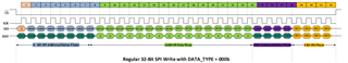
Q2:Test code indicates push one byte and read rx byte.Isn't it necessary to send complete (0x93,0x00,0x00,0x0f) and then after TMAG
checks the frame crc and responds with 32 bit response ,micro initiates read.
Q3:How to understand rx frame. we are sending(CMD0 =0,CMD1=0).Are STAT bits included even for above command.
Q4:We are interfacing TMAG with rh850fl1 micro.In read register(miso) of spi channel (16 bit data can be stored)and interested in
angle measurement(magnet,spi,actual device/system/sensor configurations are ready).we want to see SPI data formats are correct and then
proceed with sending actual configuration(continuos active conversion mode..etc)
so what could be proper way to send command.send 0x93 ,0x00 and then read miso response and send 0x00,0x0f read miso response?
Thank You,
P Tulasi Krishna.
P Tulasi,
Q1: As long as the device is not put into deep sleep mode or powered down, it is not necessary to re-initialize the configuration. Once the device is setup, you may read any SPI register as needed without sending additional writes.
Q2: The CRC bits at the end of any TX event need to be correct for the TMAG to latch the incoming data. On read events, the host may be configured similarly to check the incoming CRC from TMAG using the same method. If a read is initiated, TMAG will shift data out onto SDO without having received a valid CRC from the host. Once configured, no register writes are necessary to cause TMAG5170 to output data.
Q3:The CMD0 bit is used in trigger mode to specify whether the SPI trigger will be set as the completion of the transaction. CMD1 bit is used to determine the output on STAT[2:0] during the next communication. Since the timing of the CMD bits overlaps STAT[2:0], it would not be possible to force this update on the same frame.
Q4:It sounds as if you intend to stop mid transaction to analyze the first 16 bits, before taking action to complete the end of the communication. This would require keeping the CS line low without causing the device to timeout on the communication. During this time the SCLK input would need to pause for your calculation. The purpose of the CRC at the end of both SDO and SDI is to help ensure proper data transaction. Added with the FRAME_STAT bit in the SYS_STATUS register, it might be easier to verify SPI transactions are valid. If you ever detect STAT11 = 1 or FRAME_STAT = 1, then you would have reason to believe the SPI frame was not the correct format.
Thanks,
Scott
Hi Thank you.
we have made some progress and seems we are able to communicate with sensor.our connection looks like below
we started with simple system config 0x02,0x00,0x00,0x00
device config 0x00,0x00,0x00,CRC
and then started to change the operating mode to continuos with below configuation
0x02,0x00,0x00,0x00
device config 0x00,0x00,0x20,0x0d
and captured sys status SPI response as shown below with cmd (0x8e,0x00,0x00,0x05).verifed CRC is matching with calculated CRC but seems it's not changing to ACTIVE mode
and we see response is same for most of the status registers i.e 0xE0,0x00,0x00,0x8A(first line being micro command,second line is clock and third is sensor response.During this time CS is pulled and later pulled high which is not represented in image).
what could be the possible problems to debug further.
(SPI,polarity,phase,CRC,connections..etc).
Thanks,
P Tulasi Krishna.
P Tulasi,
I'm glad to see you're making progress. Looking at the SDO we see the following bits at 1:
Based on this I expect a CRC Error on the input on the previous frame. For the commands you have shared, I get the following CRC results:
The CRC codes from your entries match my calculations.
Based on this, I assume your CRC algorithm is running correctly, so the next likely place to check might be the SPI polarity settings. The datasheet indicates that SDI is transmitted at SCK rising edge
And that SDO is shifted out with each rising edge
From what I see in your scope capture, this appears to match as well. So the immediate cause is not clear to me, but we do know that the device is not latching writes because it perceives a CRC fault. I would recommend tracking this first bit on each communication and for debugging you could try to disable the CRC with this command on the first transmission:
0x0F000407
The device will latch the data as it receives it and will ignore any CRC faults. If this is received correctly, you should not see STAT11 go high, and then you should be able to read back to confirm your register settings match your writes.
Can you try these steps and let me know what results you get?
Thanks,
Scott
Hi,
we have same response.For simplicity, I just have written CRC disable(0x0f,0x00,0x04,0X07) one time after powerup .I have followed up with continuous reading command of system status as shown in below screenshot and the response is (0xe0,0x00,0x00,0x8a) same as above.so can i understand that even CRC disable write is also not accepted by sensor?
few more points:
a) I am probing only clock and sensor response and I see below result for same code(only change is one probe is leftout).
which is translating to 0x40,0x80,0x00,0x05.Not sure why it is different from above but this frame is also matching calculated and received CRC.
and no indication of STAT11(CRC bit) being set).But 0x80 indicates alert bit being set and upon seeing pin8 of sensor it is always high alert output.
b)we are making chip select(IO pin from micro) low at Tms. and initiating transmission at T+1ms and making CS high at T+2ms in OS 1ms task.
Thanks,
P Tulasi Krishna.
P Tulasi,
The error code appearing after the first command would imply that the CRC disable is not being accepted. This suggests a problem with the phase or polarity is likely to blame.
I captured a valid communication on the EVM:
From this it looks like the device is expecting data on SDI to be ready to latch at the rising edge. Please try updating the SPI format to match and try again.
Thanks,
Scott