This thread has been locked.

If you have a related question, please click the "Ask a related question" button in the top right corner. The newly created question will be automatically linked to this question.

LDC1101: LDC1101 and LDC tools

Part Number: LDC1101
Other Parts Discussed in Thread: LDC1001, , , LDCCOILEVM, LDC1614, LDC1612, LDC1312, LDC1000EVM

Hi,
I'm very confused.
I need to sense a metal object about 20-30mm far from the sensor.
And I have space constrains so the sensor diameter must be 15-20mm max.

I just need to sense the presence of the metal object. No need for precision.
But I need to check if the object is made of metal, to avoid false detections.

So for what I read the best option for me are the LDC1001 or the LDC1101. So I can check both Rp and L.

Now I'm trying to make some calc with the LDC tools spreadsheet, but by changing the target distance I don't get a change in Rp or in frequency.

I got something only if i go to a very low impedance, about 1uH, with a 1 layer sensor with few turns 5-7.

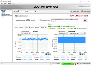
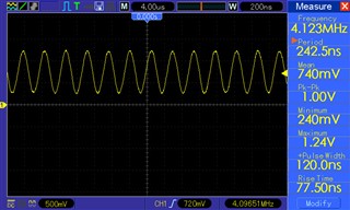
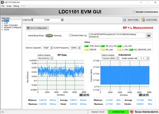
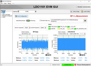
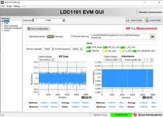
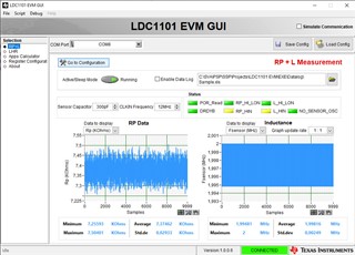
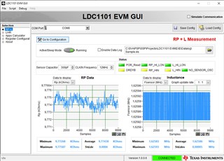
I also made some test with the eval board LDC1101EVM and some piece of ferrite sheet to shield the sensor, but this don't seem to increase the sensing distance.

What I'm doing wrong?

  • Hello, 

    For avoiding false detections, what is the use case that you would expect to cause a false positive? In addition, is there a specific metal that you have for your target or could it be a range of different metals? LDC responds to conductive material in general and is more responsive to metals with higher conductivity like copper or aluminum.

    The change in the frequency of the sensor would be very minimal with a distance that is 1.5-2x the coil diameter away from the sensor so the excel tool may not display it depending on how many digits you look at. Can you share the coil design you are calculating for? What is the capacitance that you are using with your sensor? 

    Best Regards, 

    Justin Beigel

  • Hi,

    My target is something like that:
    www.fimoworld.com/.../mef.pdf
    Stainless steel AISI 304. It is about 20mm of diameter, 150 mm length. Inner diameter about 18mm.

    The bar fits inside a plastic housing. The sensor is placed on the housing. Glued or taped, probably.

    I need to sense when the bar is correctly fitted in the housing.
    I am worried about metal object near the sensor.

    The plastic housing is a bit thick, so I need to sense the bar about 15-20mm far from the sensor. But I don't have a precise data about that. My guess at the moment is that the most far distance is 30mm.

    My plan is to put a ferrite sheet on the back of the sensor.
    As explained in the article"How to shield from metal interference"
    e2e.ti.com/.../inductive-sensing-how-to-shield-from-metal-interference

    This should prevent interference from near objects.
    But also icrease the sensing range. At least for Rp, as told in this other article:
    Top three LDC1000 questions
    e2e.ti.com/.../inductive-sensing-top-three-ldc1000-questions

    I'm testing the coils of the dev board LDCCOILEVM.
    I'm trying to check if I can match the data from the excel inductance calculator, and what I get from the real sensor, with and withouth a ferrite sheet on the back of the sensor.

    But then I got very confused.
    First, the range with the ferrite don't seem to increase.
    Not in a visible manner.
    The coil carachteristic with the ferrite vary a lot.

    And with some coils, I don't get a matching value (with the excel file), even withouth the ferrite.

    For example:
    coil "S" (10mm), according to the excel file, with a 100pF capacitor I shuld have a sensor frequency of about 6.7Mhz, L about 5.46uH, Rp 9Kohm.
    But the data I get from the devboard are: 3.33Mhz, 23uH, 13.76Kohm.

    Same with other coils.

    With the coil "E" (11x6mm) the values are completely different.
    For istance, with a 100pF capacitor:
    Excel data: 8Mhz, 3,7uH, 3.89Kohm.
    Data from devboard: 4.3Mhz, 13uH, 8Kohm.

    With big coils like the "I" (46mm) I have trouble to find a suitable setup.
    In order to stay over the 500KHz i have to choose the smallest capacitor I can get, 100pF.
    But even in this case the real frequency is lower than 500KHz.
    and some time Rp became too huge.

    Clearly I'm doing something wrong.
    Of course I don't have all data for the coils, I don't know the distance between layers. But in some case, the differences are really huge.

    What I have to do in order to get the maximum distance for a coil? Lower frequency help?
    I don't need any precision for this application. I just need to check if the metal bar is in place.
    How to deal the ferrite sheet?

    Many many thanks for any help.

  • Hello, 

    For your coils that do not match the frequency of the expected calculation, a little variation is expected but can you double check the sensor frequency by viewing the waveform on an oscilloscope? This will help determine if the large discrepancy is due to something in the device settings or something related to the coil itself. 

    For the large coils like "I", these are intended for use with devices like the LDC1614 that support a sensor frequency down to 1kHz. 

    Max distance from a sensor coil comes from using a larger coil. This generally means a lower frequency as well. However, the size of your target matters as well. See https://e2e.ti.com/blogs_/b/analogwire/posts/inductive-sensing-target-size-matters for more information on this. Is your sensor looking at the curved portion of the metal bar or one of the ends? If it is looking at the curved portion, is the plastic housing also a cylinder like the target? 

    For dealing with the ferrite sheet, can you provide oscilloscope captures of the sensor waveform before and after the sheet is placed behind the PCB? 

    Lastly, based on the description of your application, I don't think you need to sense the Rp unless you are concerned about different metals being where the bar is supposed to go. You could consider one of our other devices like the LDC1612 or LDC1312. 

    Best Regards, 

    Justin Beigel

  • Hi,

    I'm looking at the curved portion of the metal bar.
    The housing is a rectangle.

    Unfortunately I cannot vary the target size, nor the target distance.

    I also have space constraints for the sensor. It is an integrated device.
    It can be removed from the housing and reused.

    I can make a coil up to 20x40mm.
    I know that only the shorter side matter for the sensing distance.
    But 20mm is not far from what I need to sense.
    If I can increase this distance a bit with a ferrite, it will be ok for me. At least for the first prototype.
    I would like to keep the Rp measurement for now. Maybe it will be handy. And I want to check the data from the prototype, when is in use.

    Probably I will make a version with the 1612, just in case.

    Is there any difference between the 1101 and the 1001 in therms of target distance?
    I know the 1001 also need an analog supply. I'm making test with the 1101 mostly because I would to avoid to put a boost converter, and the 1101 is available from some reseller.

    Here some data from the coil with more discrepancy between the Coil and the inductance calculator.
    The ferrite sheet I'm using is the Wurth 354003

    E 100pF no ferrite. Expected value from the excel: 8Mhz 3.7uH 3.89Kohm
    E 100pF no ferrite EVM GUIE 100pF no ferrite

    E 100pF with ferrite
    E 100pF with ferrite EVM GUIE 100pF with ferrite

    S 100pF no ferrite. Expected value from the excel: 6.7Mhz 5.46uH 9Kohm
    S 100pF no ferrite EVM GUIS 100pF no ferrite

    S 100pF with ferrite
    S 100pF with ferrite EVM GUIS 100pF with ferrite


    S 300pF no ferrite. Expected value from the excel: 3.9Mhz 5.461uH 3.42Kohm
    S 300pF no ferrite EVM GUIS 300pF no ferrite

    S 300pF with ferrite
    S 300pF with ferrite EVM GUIS 300pF with ferrite

  • Hello, 

    Thank you for the data. In regards to: 

    Is there any difference between the 1101 and the 1001 in therms of target distance?

    We do not recommend using the LDC1001 for new designs at this time. These two parts are similar and we suggest using the LDC1101 in place of the LDC1001 for applications that still need Rp measurements. 

    The addition of the ferrite seems to have the expected impact on the sensor waveforms. As for why they are different from the expected calculations, how are you connecting the sensors? Can you try putting the device into LHR mode and seeing if the sensor frequency is still the same? 

    Sensor frequency difference aside, are you able to get a difference in sensor frequency with the coils when you test with your metal target? I wouldn't expect a larger frequency shift once the ferrite sheet is added, but would expect to be able to detect a finer resolution of frequency since the sensor frequency is lower. 

    Best Regards, 
    Justin Beigel

  • Hi,

    As for why they are different from the expected calculations, how are you connecting the sensors? Can you try putting the device into LHR mode and seeing if the sensor frequency is still the same? 

    I checked with the sensor in LHR mode, no changes, the frequency still the same.

    I made some other measurement with the oscilloscope, because one of the waveform seems a bit wobbly.
    And the waveforms are not stable, there is some ringing. I seem to have this behavior with all coils.
    Is that normal?

    S 100pF no ferrite ringing
    S 100pF no ferrite ringing


    M 180pF no ferrite ringing
    M 180pF no ferrite ringing

    Sensor frequency difference aside, are you able to get a difference in sensor frequency with the coils when you test with your metal target? I wouldn't expect a larger frequency shift once the ferrite sheet is added, but would expect to be able to detect a finer resolution of frequency since the sensor frequency is lower. 

    I can sense up to 10mm, I don't see much change over this range.
    I can go up to 15mm with bigger coils, like "I" or "H". But those are too big for me.

    By using the 1101 in LHR mode can I extend the range?
    With the EVM GUI I don's see much improvement.
    There is some setting to change?

    If I want to design a coil to maximize the sensing range, which parameter I should consider more?
    Higher Rp? Lower inductance?
    Is ok to use a sensor capacitor of 100pF with a ferrite sheet? Or I should try to keep it higher?
    There is a frequency limit to avoid with the ferrite sheet?

    Do the ferrite thickness matter?

  • Hello, 

    The variation in the sensor amplitude is related to the device taking the RP measurement. The waveforms you shared look good to me. 

    In general, you will see less change in data the farther you get away from your sensor. Using the LHR mode would give you more resolution to detect a smaller change in the data but you will want to make sure your target interaction is still larger than the noise on the sensor. With the EVM GUI, you should be able to easily change to this mode and monitor the L data. 

    The main impact to maximizing the range of a coil is the size of the coil. Larger coils have better range and tend to be lower frequency. The Rp mainly plays into how much current is required to drive the sensor. 

    I don't see any reason why having the capacitor at 100pF would be a problem. I will double check on the ferrite sheet, but I don't think there is a frequency limit or a recommended thickness. 

    Best Regards, 

    Justin Beigel

  • Hi,

    Thanks for the help.

    About the capacitor I was asking because 100pF is the smaller value for the 1101, and I don't know how the ferrite impact on the capacitance.

    I have another question.

    I having some good results with a NFC coil, this one:
    www.molex.com/.../1462362102_ANTENNAS.pdf

    This type of antenna generally are made on one layer only.

    There is some disadvantage in have a one layer antenna?

  • Hello, 

    Having a 1 layer coil design can mean that the magnetic field generated by the coil is slightly weaker in some cases but is still a feasible design choice. If you want to know more of the changes that will happen with a 1 layer coil compared to a 2 layer coil, you can vary the number of layers in our LDC_DESIGN_TOOLS excel spreadsheet. 

    In regards to the 100pF capacitor, the main importance is to ensure that your coil frequency and Q factor are still in the recommended range for the device. 

    Best Regards, 

    Justin Beigel

  • Hi Justin.

    Thanks for the useful info.

    Did you got some info about the ferrite thickness?

  • Just another quick question.

    Today I received the LDC1000EVM.

    I noticed that there is a hole in the center of the coil.

    Is the hole having some effects on the sensing?

  • Hello, 

    The thickness of the ferrite doesn't have a significant impact on the shielding of the LDC sensor. 

    As for the hole in the center of the coil, it does not have any effect on the sensor performance. Normally, the inner diameter of the coil is just left as blank PCB but whether the FR4 is present or not doesn't have any impact on the sensor performance. 

    Best Regards, 

    Justin Beigel