This thread has been locked.

If you have a related question, please click the "Ask a related question" button in the top right corner. The newly created question will be automatically linked to this question.

FDC2214EVM: How to switch Active / Sleep mode ?

Part Number: FDC2214EVM
Other Parts Discussed in Thread: FDC2214

Hello Application Engineers,

I have FDC2214 EVM, and I want to use 3 units to make 12 channels. There is a cross-talking issue when 2 or 3 units work simultaneously. hence, I am trying to put one on active and other two on sleep (or on mute).

Firstly, I tried to use active/sleep mode on single unit as a chart below, but not successful. 
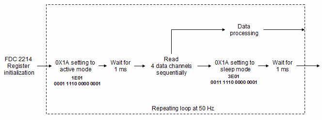
Hexadecimal value 1E01 was written into register 0X1A to active the unit followed by a 1 ms wait to ensure enough time for the setting to complete; then 4 data channels were read sequentially; then the unit was put on sleep by writing a Hexadecimal value 3E01 into the same register 0x1A followed by 1 ms wait. This process is programed to repeat at 50 Hz. 

Issue: data acquisition was successful when sleep mode setting is not in the loop.  Reading data was halted when sleep mode setting is in the loop.  I also checked if 3E01 was really successfully written into the register 0X1A using a read back coding, I got confirmation that the value 3E01 was correctly assigned to the register 0X1A. 

Could someone help me with the active/sleep mode switch setting?

  • Guoxing,

    As an experiment, could you try allowing the Wait to go longer than 1ms (10ms, 100ms) after switching from Sleep to Active?
    This may not be the final way it will be used, but it may help us figure out what is going on.

    Regards,
    John

  • Hi John,

    As instructed, I tried different wait times after switching from Sleep to Active, the results are as shown below:

    Wait time (ms)               Channel data update

    1 or 2                             No channel works

    5 or 10                           CH0

    15                                  CH0, CH3

    20 or 25                         CH0, CH2, CH3

    30 and above                CH0, CH1, CH2, CH3

    Conclusion: wait time must be greater than 30 ms to make all 4-channel work properly, which is significantly longer than the spec of 0.05 ms. 

     Is there any way to make it work at a wait time less than 5 ms, preferably 1 ms?

    Thanks,

    Gu

  • After a few times tries, the 30 ms wait does not work anymore, the minimum wait time need to be 100 ms to make all 4 channels work.

  • Gu,

    I will need to check with one of my colleagues about your observations.
    I will provide an update tomorrow.

    regards,
    John

  • Hi John,

    I found an old post talking about the similar observation as I have now., I am wondering If you could find out if a final solution was provided to the person who wrote the post.

     
    https://e2e.ti.com/support/sensors-group/sensors/f/sensors-forum/998201/fdc2214-sleep-mode-active-mode-for-low-power-application

    Gu

  • Guoxing,

    Thank you for finding that post.
    The next step in that thread was for the poster to provide some data, which apparently did not happen.

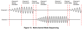
    What you are seeing may be dependent on the device settings. For example, section 9.3.2 of the data sheet talks about the dwell time interval for each channel (page 16) as the sum of the sensor activation time, the conversion time and the channel  switch delay, and the subsequent paragraphs discuss how these parameters can be calculated.
    Could these need to be optimized for your application?

    Also, would it be possible to look at the sensor signal with an oscilloscope and post the image to this thread?
    It  might be useful to see what that waveform looks like, and how quickly it ramps up and down.

    Regards,
    John

  • Hi John,

    I went through all sections of the datasheet many times. However, I do not have an oscilloscope, hence I am facing the same situation as the guy who posted the thread before. As common users, most of us do not have an oscilloscope. 

    My parameter's settings work fine without the sleep involvement. active/sleep switch should be independent to other parameter's settings.

    Could you please provide me a setting of all parameters that active/sleep switch works on your side? then, I can repeat your settings on my side to see if I can get it over?

    Best regards,

    Gu

  • Hello, 

    Oscilloscopes are a very handy tool and laptop USB based ones like PicoScope or the Analog Discover Module can offer cheaper alternatives than some lab bench options. 

    Lab equipment aside, you can still calculate the timings based on your device settings. For giving suggested parameters, it would be best to know the timings involved with your sensor. I have the following questions to help clarify: 

    • Are you using the internal or external reference clock? 
    • What is your settlecount register setting? 
    • What kind of sensor are you using with the device? 
      • Is it the same sensor for all 4 channels? 
      • Did you change any of the L or C components on the sensor channels? 

    Lastly, if you take multiple measurements when you wake up the device do you see the same results for the channel data? For example, the procedure would be altered to the following: 

    Wake device -> Wait for _ms -> read data for all 4 channels (2, 5, or 10) times -> sleep device -> wait -> repeat

    Thank you, 

    Justin

  • Hi Justin,

    Thank you for your reply.

    It would be nice to have a picoscope. here below are my settings

    Clock: external

    SettleCount: 0x0400

    Sensor: Capacitive, same sensor for all 4 channels. 

    L or C components: L was changed to 127 uH to bring frequency to approximately 1 MHz at which highest effective number of bits can be achieved.

    I observed value change after waking up. the values with or without sleep activation were in the expected range.  but the wait time must be >= 100 ms

    I used same sequence as your suggestion to wake/sleep the unit, the only thing is that I just read one time for all 4 channels in between active and sleep. 

    Finally, I need to make 3 units working together, reading more time on one unit and then switch to other will not fit my application.  I even changed the wait time (30 to 50 ms) after sleep to see if it works, this wait time could be used to active other 2 units. It did not work.


    Best regards,

    Gu

  • Hello, 

    The reason for taking multiple measurements after waking up is to ensure consistency in the measurement immediately after waking the device. If it isn't possible to look at the waveform on a scope, then this will help give us some insight into what might be happening to cause the issue you are seeing. Collecting 5 or 10 samples instead of just a single sample for all 4 channels should be enough to help us. 

    And to clarify, this issue is occurring on all 3 units, correct? 

    Best Regards, 
    Justin 

  • Hi Justin 

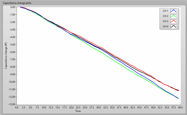
    Here included is a screen shot of the data collected after waking up. I do not see any problem with the data consistency. The descending trend was caused by room temperature fluctuation.  The data was collected when the sensors were hold still in the air. 

    Yes, the issue is with any one of the unit. 

    Gu

  • Hello Gu, 

    Thank you for the additional information. I am still looking into this and will have more information for you by the end of the week. 

    Best Regards, 

    Justin Beigel

  • Hello Gu, 

    If you are using the RCOUNT at 0xFFFF as you mentioned in another thread, this may be a timing violation for collecting data. Based on your SETTLECOUNT, the sensor activation time would be roughly 0.4ms. With RCOUNT at the max value, the sensor conversion time is roughly 26ms. There is also a small channel switching delay, 0.8us for the external clock on the EVM. With these combined, sample time for all 4 channels will be above 100ms. Based on these timings, it would make sense that you only get consistent data with a 100ms delay inserted in your routine. 

    Instead of having a wait in your code, you could poll the DRDY bit of the STATUS register to see when data is ready to read: 

    Or you can set DRDY to report on INTB and wait for the GPIO signal to read the data. 

    Best Regards, 

    Justin Beigel

  • Hi Justin,

    You are right that the conversion time for the 4 CH is above 100 ms. precisely, 104.8 ms. I tried 200 ms wait time for the loop to repeat, meaning all channels had sufficient time to do their conversion, then they were put to sleep, However, the issue remains, I still need to put 100 ms wait between the unit activation and channel data reading to switch active/sleep mode.

    Could you please let me know what Rcount setting to make the wake-up time 0.05 ms? 

    I appreciate all your efforts.

    Gu

  • Hello Gu, 

    The wakeup time of 0.05ms noted in the datasheet is for the device to wake up and start the channel conversion. The time for the device to sample all channels and provide data is determined by the RCOUNT and SETTLECOUNT settings. Achieving 0.05ms for having data available to read is not possible. 

    Equation 3 gives you the sensor activation timing based on your SETTLECOUNT setting: 

    For your current implementation, this is 0.4096ms. If you decrease this to save time, you need to ensure you are still following the following guideline: 

    The channel conversion time is impacted by RCOUNT and can be calculated using equation 5 in the datasheet: 

    Keep in mind that as RCOUNT decreases, the noise in the measurement will increase. 

    Best Regards, 

    Justin Beigel

  • Hi Justin,

    It seems that it is not possible to use active/sleep switch for my application as I need the highest signal-to-noise ratio.

    Alternatively, I am wondering if we can use different frequencies for different units to avoid cross-talking. I want to keep one unit at approximately 1MHz.

    Could you please suggest other two fervencies for other two units so that 3 of them can work without significant interference. I would like to use the minimum frequency gap for this application. The operational frequency can be shifted by changing both inductor and/or capacitor.

    Best regards,

    Gu 

  • Hello Gu, 

    You can reduce crosstalk by having a frequency shift of at least 20% between units. So for your second and third units, you could have frequencies of 1.2MHz and 1.44MHz, but using a higher frequency shift will further reduce crosstalk. When changing the frequencies for your other units, make sure you consider the impact it will have on the Q factor of your sensor as well to make sure it isn't dropping too low. 

    Best Regards, 

    Justin Beigel

  • Hi Justin,

    I will try it. it will take me some time to modify the units. I am closing this conversation at this time and may come back to you in the future.

    Thank you for your helps,

    Gu