This thread has been locked.

If you have a related question, please click the "Ask a related question" button in the top right corner. The newly created question will be automatically linked to this question.

PGA970: Erratic Excitation waveform

Part Number: PGA970

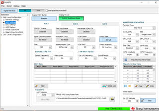
I'm having an issue with the excitation of a PGA970 on an evaluation board.  The excitation was a nice sine wave and while attempting to test the loop back function, the waveform became erratic, see below.
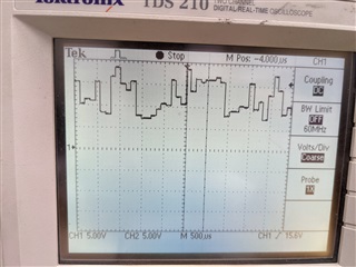
  • Hi Alex,

    Welcome to our e2e forum!  Are you using our evaluation board?  If not, can you share your schematic with us?

  • I am using the evaluation board

  • Hi Alex,

    After turning off the loopback function do you still see the waveform that you shared above, or does it go back to the clean sine wave you saw originally? Can you please share the waveform gain settings, and S1/S2 gain settings that you are using?


    Thank you,
    Scott

  • I went to test again this morning and when trying to use the op amp to boost the output, I get no wave form out and a very hot op amp.  Using the jumpers, I took the op amp out of circuit and got the same wave form I posted initially.  The S1 and S2 gains are both at 1.0.

  • I went to test again this morning and when trying to use the op amp to boost the output, I get no wave form out and a very hot op amp.  Using the jumpers, I took the op amp out of circuit and got the same wave form I posted initially.  The S1 and S2 gains are both at 1.0.

  • Hi Alex,

    Just to clarify, after the opamp was removed you are seeing the digitized-looking waveform from the first post? And the waveform data table has not changed at all between when you were able to get a clean sine wave and now? Have you noticed if the current draw from the EVM is any different from when the waveform looked correct? And can you check the voltages on AVDD and DVDD? Also, please check the PI/PE pins with a scope.

    With the loopback disabled, are you able to get reasonable readings from the S1/S2 inputs, or have those been affected as well?

    Thanks,
    Scott

  • Correct, the digitized waveform was with the op amp removed.  I haven't changed the waveform table and the current draw went up a little bit, maybe 10mA initially.  Checking it now, the current draw appears to be the same.

    AVDD- 2.977 VDC

    DVDD - 1.851 VDC

    The PI and PE pins show a digitized waveform as well.  I don't currently have an LVDT to test S1 and S2 without the loopback.  Also, I'm not sure I was ever able to get the loopback working properly.  That is what I was attempting when the excitation went from a sinewave to digitized.

  • It seems like the device isn't experiencing any power issues. Have you checked if the waveform RAM has been successfully populated with the data from the table? You can see this on pages 8-9 in the Data/Waveform RAM section of the GUI, and compare to the table that is populated on the ADC page.

    Regards,

    Scott

  • Pages 8 and 9 read almost all 202s.

  • Hi Alex,

    Have you been able to get back to the original sine wave at all?  We need to try and understand why you would have had 'very hot op-amps'.  Can you describe how you had the jumpers configured?

  • Hi Alex,

    The 202s don't match the table on ADC settings page. Can you try writing those values back into RAM, disabling generator and re-enabling it again? I can't remember if you need to take the device in and out of Microcontroller mode to get everything copied over and enabled but try that as well. We need to have the new values put into RAM and then pulled out of RAM to set it.

    As for the hot op amps, I would see the op amp is damaged with some impedance test on the pins, or (after disabling the generator) checking the current drawn by VPWR. I hope the waveform generator was not damaged but they are connected to the same node so it is a possibility. 

    Best,

    -Cole