This thread has been locked.

If you have a related question, please click the "Ask a related question" button in the top right corner. The newly created question will be automatically linked to this question.

AFE3010-EVM: AFE3010-EVM test of the Relay

Part Number: AFE3010-EVM
Other Parts Discussed in Thread: AFE3010

Hi Team,

Regarding the test of the AFE3010 experiment board, we found a question, "When we actually take the relay to test, we will hear that the relay cannot be continuously turned on, and there will be a click of the switch", of this relay are there a suggested part number?

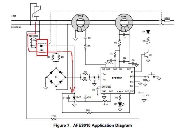
Please refer to the red line in the figure below. We found that the Relay coil power supply (Solenoid) part, the circuit diagram, and the experimental evaluation board only put a diode (D2) for rectification. How does this configuration maintain the continuous excitation of the relay coil?

  • Hello Rock,

    The device was designed to pull current through solenoid during the half-line cycle where HOT > NEUTRAL. This is actually all the time the SCR/solenoid need to actuate typical electromechanical load switches. Keep in mind that SCR will go active high (sourcing current mode) as soon as device detects a fault/self-test failure even if HOT< NEIUTRAL and SCR will remain active for at least one full line cycle. Even though this could mean there can be an inherent ~8ms delay, the device has fast enough detection to still achieve overall total trip times required by UL 943 even with the largest fault currents required.

    We do not have any suggested part numbers for the solenoid as these components and their assembly can be highly specialized/proprietary, and not to mention variable, given the complexity and variability when it comes to the electromechanical connection of solenoid actuation to latching open a mechanical load switch.

    You could use a relay (e.g, double pole double throw) to act as the load switch, but then you would need to make adjustment to our typical recommended schematic. For example, would you pull current through a the relay coil via an SCR component or would you use the SCR pin directly drive current (~2mA) through the coil. If you go with the former option, then you could replace the solenoid with a resistor that reduces current to a safe enough level that will not burn relay coil. If you go with using SCR pin to drive relay directly, then you do not need the SCR self-test and thus you would want to float the SEL pin. See section 7.4.1 of datasheet.

    If you have any more questions, do not hesitate and please post them here to the forum.

    Sincerely,

    Peter