This thread has been locked.

If you have a related question, please click the "Ask a related question" button in the top right corner. The newly created question will be automatically linked to this question.

OPT3001-Q1: BOARD LAYOUT and STENCIL DESIGN

Genius 4840 points
Part Number: OPT3001-Q1

Our customer has some question about this item.

When they saw this light sensor EXAMPLE BOARD LAYOUT and EXAMPLE STENCIL DESIGN, there was an instruction to open a Via in the center
(Page 42-43), please refer following datasheet.

https://www.ti.com/lit/ds/symlink/opt3001-q1.pdf


So they would like to ask the following 3questions, could you please advise us.

1.What purpose is this hole used for?
2.Can this part be used for FPC with single-sided wiring?
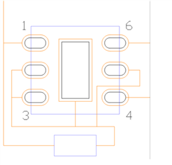
3.Is there no problem if the wiring is laid between the pins?
 (Image of running a line between 4pin and 5pin below)

regards,

Kura

  • Hello Kura,

    1) The via used to electronically connect the thermal pad to ground.  More information can be found in section 11.1 in the datasheet.  This type of package is used across devices and used for thermal release.  However, this devices pulls single digit uA and the via isn't not really needed.

    2) There should not be a problem using this device with a single-sided FPC.

    3) It appears that you have the int pin connected to GND.  Is there a reason for that?

    Rahland

  • Question 3 reply contents

    They understand that it is a part that can be used even with a single-sided FPC.
    The reason why INT(5pin) is connected to GND is based on the customer's circuit drawing.
    Is this connection not recommended? What kind of problems do you encounter?

    regards,

  • Hello Kura,

    Connecting INT to GND is not usually recommended.  If unused, the INT pin can be left floating.

    Rahland