This thread has been locked.

If you have a related question, please click the "Ask a related question" button in the top right corner. The newly created question will be automatically linked to this question.

IWR1843BOOST: Problem using DCA1000EVM

Part Number: IWR1843BOOST
Other Parts Discussed in Thread: DCA1000EVM, , IWR1843, UNIFLASH

Hello everyone!

I am recently starting to get my hands on capturing raw data using the DCA1000EVM board with an IWR1843BOOST device. I have followed the video-tutorial and read the user-guide and documentation for the DCA1000EVM, but I am not being able to connect to the IWR1843BOOST through SPI. I am able to connect to the FTDI and RS232 ports, but not to the SPI. I have installed all the drivers, and my computer detects the same COM ports as in the user-guide.

Both devices are brand new. I have flashed the out-of-box demo in the IWR1843BOOST to test it. And I am using mmWave Studio with the MSS and BSS files provided in the installation files. But when I try to connect through SPI (step 5 in mmWave Studio RadarAPI) the applications hangs and closes.

Here is a picture of the hardware configuration:

IWR1843BOOST

  DCA1000EVM

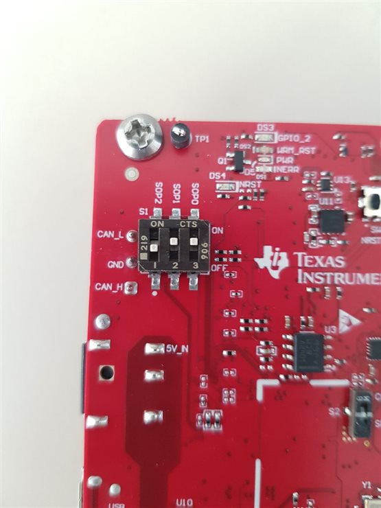
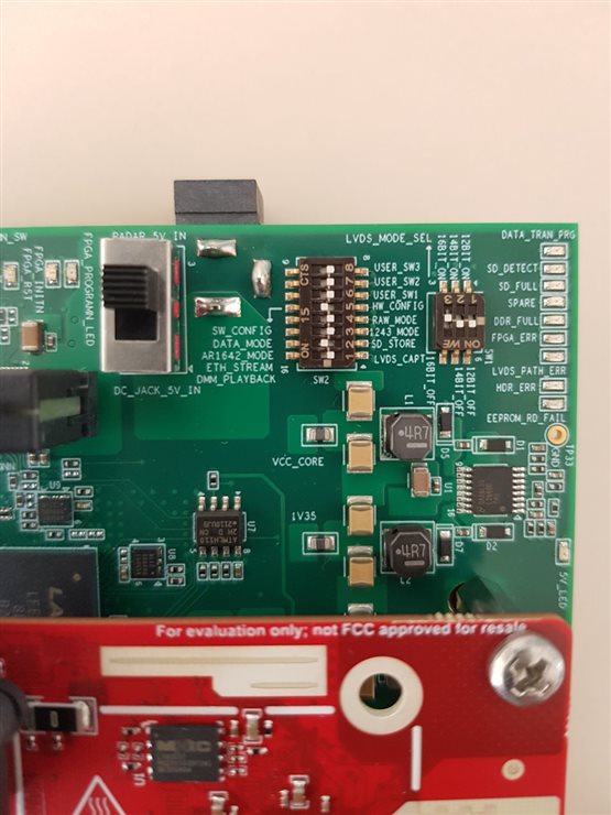
I have read other posts and tried their solutions, but none worked. And some had a previous version of the board because the SOP modes had pins instead of switches. I also tried to connect the IWR1843BOOST without the DCA1000EVM to mmWave Studio with no luck. The only difference with respect to the user-guide is that I am powering the DCA1000EVM using the radar 5V in from the 60 pin radar connection instead of having a separate power supply. I do not have another one at the moment. I hope this is not a problem.

Is there anything I am missing?

Thanks in advance!

Felipe P.

  • Hi Felipe,

    Before we start discussing the configuration of the DCA1000, I just want to ensure that this is the correct path to go down. What type of data are you looking to receive for the radar sensor? Without the DCA1000, it is possible to get many various kinds of data from the radar device via the serial connection such as a point cloud or heatmap. The DCA1000EVM and mmWaveStudio are ONLY necessary if you desire raw ADC data. This additional EVM is needed to support the very high volume of data which is produced when capturing this raw data. If you are not very familiar with Radar Data processing, it will likely be much easier to start with the data which is output without the DCA1000EVM, which is already processed by the ARM core and DSP on the device using the algorithms in our demos. Typically, raw data is only needed when you are hoping to develop an entire radar processing chain from scratch.

    Let me know if this makes sense, and if this is what you are looking for, we can help you debug the issue with your setup.

    Best Regards,
    Alec

  • Hi Alec,

    I am familiar with radar point clouds and heatmaps provided by the demos. I am part of a physics research group that has been working with TI's radars for a while using the demos and we are trying to get raw signals to obtain as much information as possible from them. It is easier for us to implement our own DSP algorithms than trying to modify the sources of the demos.

    Best,

    Felipe.

  • Hello Felipe,

    I can help you with DCA1000 error debugging. First off I would like to point you to our DCA1000 User Guide located in our Industrial Toolbox for mmWaveSensors (https://dev.ti.com/tirex/explore/node?a=VLyFKFf__4.12.0&node=A__AGTrhNYW8jE6cMxbovlfaA__com.ti.mmwave_industrial_toolbox__VLyFKFf__4.12.0).

    Within the "Need More Help?" section is the DCA1000 Debugging Handbook. The most common errors involving the DCA1000 is covered in this debugging handbook. Can you send me the log that includes the exact error when you try to connect to SPI? The error code (returned X) can mean different things and can potentially help me with debug.

    I want to let you know from the pictures you have taken that USER_SW1 (Switch 6) must be in the ON position and in your picture it is off. Also make sure your IWR1843 is in "Development Mode". This is SOP0 and SOP2 being on with SOP1 being off.

    Best Regards,

    Pedrhom Nafisi

  • Hello, if I configure the IWR1843BOOST with SOP0 and SOP2 on and SOP1 off (which is flash programming mode as stated in the user guide), I am unable to connect to the RS232 port with error "[RadarAPI]: Error: Connection failed: Calling_ConnectTarget returned 3". Only when in debug mode (011, SOP2 SOP1 SOP0) I can establish this connection correctly.

    With respect to the DCA1000, I have enabled the USER_SW1 switch as suggested, but the problem is still not solved. I have tried to see the error code, but the program freezes and then it is automatically closed. I have the log until that point:

    GM: Constructor
    GM: Fri Oct 14 09:32:17 2022
    RSTD.Transmit("/Settings")
    [09:32:18]  
    [09:32:18]  ### Running Startup script: "C:\ti\mmwave_studio_02_01_01_00\mmWaveStudio\Scripts\Startup.lua" ###
    [09:32:18]  RSTD.SetAndTransmit ("/Settings/Scripter/Display DateTime" , "1")
    [09:32:18]  RSTD.SetAndTransmit ("/Settings/Scripter/DateTime Format" , "HH:mm:ss")
    [09:32:18]  Scripter ignored: Attempt to UnBuild() again or before Build.
    [09:32:18]  RSTD.SetVar ("/Settings/Clients/Client 0/Dll" , "C:\\ti\\mmwave_studio_02_01_01_00\\mmWaveStudio\\Clients\\\\LabClient.dll")
    [09:32:18]  RSTD.SetVar ("/Settings/Clients/Client 0/Use" , "TRUE")
    [09:32:18]  RSTD.SetVar ("/Settings/Clients/Client 1/Use" , "FALSE")
    [09:32:18]  RSTD.SetVar ("/Settings/Clients/Client 2/Use" , "FALSE")
    [09:32:18]  RSTD.SetVar ("/Settings/Clients/Client 3/Use" , "FALSE")
    [09:32:18]  RSTD.SetVar ("/Settings/Clients/Client 4/Use" , "FALSE")
    [09:32:18]  RSTD.SetVar ("/Settings/AL Client/AL Dll" , "C:\\ti\\mmwave_studio_02_01_01_00\\mmWaveStudio\\RunTime\\SAL.dll")
    [09:32:18]  RSTD.SetVar ("/Settings/Clients/Client 0/GuiDll" , "")
    [09:32:18]  RSTD.SetVar ("/Settings/AutoUpdate/Enabled" , "TRUE")
    [09:32:18]  RSTD.SetVar ("/Settings/AutoUpdate/Interval" , "1")
    [09:32:18]  RSTD.SetVar ("/Settings/Monitors/UpdateDisplay" , "TRUE")
    [09:32:18]  RSTD.SetVar ("/Settings/Monitors/OneClickStart" , "TRUE")
    [09:32:18]  RSTD.SetVar ("/Settings/Automation/Automation Mode" , "false")
    [09:32:18]  RSTD.Transmit("/")
    [09:32:18]  RSTD.SaveSettings(): Settings saved to "C:\Users\GISS\AppData\Roaming\RSTD\config.xml"
    [09:32:18]  RSTD.Build()
    [09:32:18]  RSTD.SaveSettings(): Settings saved to "C:\Users\GISS\AppData\Roaming\RSTD\config.xml"
    [09:32:18]  RSTD.Transmit("/")
    [09:32:18]  RSTD.AL_Build()
    [09:32:18]  RSTD.AL_LoadXml()
    [09:32:18]  RSTD.Transmit("/")
    [09:32:18]  RSTD.AL_Init()
    [09:32:18]  RSTD.Clients_Build()
    [09:32:18]  GM: Init
    [09:32:18]  GM: Loaded 'C:\ti\mmwave_studio_02_01_01_00\mmWaveStudio\Clients\\LabClient.dll'
    [09:32:18]  GM: 1 Guest (s) init
    [09:32:18]  GM: 1 Module(s) init
    [09:32:18]  GM: 2 Tab   (s) init
    [09:32:18]  RSTD.Client_LoadXml()
    [09:32:19]  [RadarAPI]: ar1.selectRadarMode(0)
    [09:32:19]  [RadarAPI]: Status: Passed
    [09:32:19]  Matlab Runtime Engine is installed
    [09:32:19]  [RadarAPI]: Starting Matlab Engine..
    [09:32:39]  [RadarAPI]: Matlab Engine Started!
    [09:32:44]  [RadarAPI]: ar1.selectCascadeMode(0)
    [09:32:44]  [RadarAPI]: Status: Passed
    [09:32:44]  [RadarAPI]: ar1.LoadSettings('C:\Users\GISS\AppData\Roaming\RSTD\ar1gui.ini')
    [09:32:44]  [RadarAPI]: Error: Índice fuera de los límites de la matriz.
    [09:32:44]  Trace:
    [09:32:44]     en AR1xController.ScriptOps.getMatlabPostProcVersion()
    [09:32:45]  TESTING = false
    [09:32:45]  RstdNet: Port 2777: Listening..
    [09:32:45]  
    [09:32:45]  ***Script completed successfully.***
    [09:37:09]  [RadarAPI]: Opening Gpio Control Port()
    [09:37:09]  [RadarAPI]: Status: Passed
    [09:37:09]  [RadarAPI]: Opening Board Control Port()
    [09:37:09]  [RadarAPI]: Status: Passed
    [09:37:10]  [RadarAPI]: ar1.FullReset()
    [09:37:10]  [RadarAPI]: Status: Passed
    [09:37:11]  [RadarAPI]: Closing Board Control Port()
    [09:37:11]  [RadarAPI]: Status: Passed
    [09:37:11]  [RadarAPI]: Closing Gpio Control Port()
    [09:37:11]  [RadarAPI]: Status: Passed
    [09:37:11]  [RadarAPI]: ar1.SOPControl(2)
    [09:37:11]  [RadarAPI]: Status: Passed
    [09:37:13]  [RadarAPI]: ar1.Connect(6,115200,1000)
    [09:37:14]  [RadarAPI]: ar1.Calling_IsConnected()
    [09:37:15]  [RadarAPI]: ar1.SelectChipVersion("AR1642")
    [09:37:15]  [RadarAPI]: Status: Passed
    [09:37:15]  [RadarAPI]: ar1.SelectChipVersion("AR1642")
    [09:37:15]  [RadarAPI]: Status: Passed
    [09:37:15]  [RadarAPI]: ar1.deviceVariantSelection("XWR1843")
    [09:37:15]  [RadarAPI]: Status: Passed
    [09:37:15]  [RadarAPI]: ar1.frequencyBandSelection("77G")
    [09:37:15]  [RadarAPI]: ar1.SelectChipVersion("XWR1843")
    [09:37:15]  [RadarAPI]: Status: Passed
    [09:37:16]  Device Status : XWR1843/QM/SOP:2/ES:2
    [09:37:16]  [RadarAPI]: ar1.SaveSettings('C:\Users\GISS\AppData\Roaming\RSTD\ar1gui.ini')
    [09:37:45]  [RadarAPI]: ar1.DownloadBSSFw("C:\\ti\\mmwave_studio_02_01_01_00\\rf_eval_firmware\\radarss\\xwr18xx_radarss.bin")
    [09:37:45]  [RadarAPI]: Downloading BSS Patch RPRC Binary..
    [09:37:53]  [RadarAPI]: ar1.GetBSSFwVersion()
    [09:37:53]  [RadarAPI]: BSSFwVersion:(02.00.00.01 (05/10/17))
    [09:37:54]  [RadarAPI]: ar1.GetBSSPatchFwVersion()
    [09:37:54]  [RadarAPI]: BSSPatchFwVersion:(01.02.05.02 (30/04/19))
    [09:37:55]  [RadarAPI]: ar1.DownloadMSSFw("C:\\ti\\mmwave_studio_02_01_01_00\\rf_eval_firmware\\masterss\\xwr18xx_masterss.bin")
    [09:37:55]  [RadarAPI]: Downloading MSS RPRC Binary..
    [09:38:07]  [RadarAPI]: ar1.GetMSSFwVersion()
    [09:38:07]  [RadarAPI]: MSSFwVersion:(01.02.05.02 (16/07/19))

    I have had a look at the user guide you pointed and checked to have installed all the requirements. I have recorded the screen of my computer to find the error code before mmWave studio closes and it is this one: "Status: Failed, Error Type: RESP TIMEOUT".

    Thank you!!

    Best,

    Felipe P.

  • Hello Felipe,

    So there are three SOP modes that the user generally will use with the mmWave sensor. First is flashing mode which is when you use Uniflash to flash a .bin file. The second is functional mode where you send CLI commands to start the sensor. And the third is the development mode which is what you need for the entirety of time with using a DCA1000. SOP configuration for each mode is different per device, and you are correct that 011 is development mode for the IWR1843, my mistake.

    So with your current error where you get a RESP TIMEOUT, I have seen this solved in the past via erasing the flash and clearing everything that is on the mmWave sensor via Uniflash before trying DCA1000 again. Especially since you get the timeout on MSS and not BSS. You can find how to erase the flash here: https://software-dl.ti.com/ccs/esd/uniflash/docs/v5_0/quick_start_guide/uniflash_quick_start_guide.html

    Best Regards,

    Pedrhom Nafisi

  • Hello Pedrhom,

    I have erased the flash but SPI connection is still not working. This time I do not see any errors before mmWave Studio is closed.

    Should I flash any particular firmware on the IWR1843BOOST after erasing the flash?

    Best,

    Felipe P.

  • Hello Felipe,

    When you say mmWave Studio is closed, are you saying it is crashing or an error is not presented when you try to proceed after attempting SPI connection? Does BSS and MSS flashing complete or does it still hang on one of them? When our sensors are shipped, they come preflashed with the Out of Box demo binary which can also be found in our Industrial Toolbox for mmWave Sensors. When you choose the MSS and BSS evaluation firmware for your device, you are flashing a binary all the same with the only difference being that you are flashing the memory one section at a time.

    Best Regards,

    Pedrhom Nafisi

  • Hello Pedrhom,

    When I say that mmWave Studio is closed I mean that after flashing BSS and MSS is completed, I click "SPI Connect" and after a while the GUI crashes and the program is closed. I cannot see if an error is being logged because it all happens very fast. However, I recorded my computer's screen and that is when I saw the "Status: Failed, Error Type: RESP TIMEOUT" message I wrote a couple days ago. I am attaching a video file showing this.

    https://drive.google.com/file/d/1IsqGd_Pt3BqacTAhBjILhuwMYo7-Tg3j/view?usp=sharing

    Thank you!

    Best,

    Felipe P.

  • Hello Felipe,

    Thank you for the video, it helps a lot. Everything you did was in order on the software side. Could you try reinstalling mmWave studio or possibly trying another computer? A full freeze like that rather than a crash makes me thing something is wrong on the computer end and not on the DCA1000 or sensor, otherwise you would get an error. Especially since you tried erasing the flash and still had the same problem.

    Best Regards,

    Pedrhom Nafisi

  • Hello Felipe,

    One more thing to look at. Near your SOP switches should be a MUX switch that is on or off. Can you confirm that it is set to SPI? If not set to SPI and try again.

    Best Regards,

    Pedrhom Nafisi

  • Hello Pedrhom,

    It was this switch. I set it to SPI and now SPI connection is properly established.

    Thank you so much for your time!!

    Best regards,

    Felipe P.