This thread has been locked.

If you have a related question, please click the "Ask a related question" button in the top right corner. The newly created question will be automatically linked to this question.

AWR6843: AWR6843

Part Number: AWR6843

Hi,

Based on the AWR6843 Datasheet (Serial No: SWRS248D), we have differential LVDS Data Lanes, Clock lane and Frame clock lane.

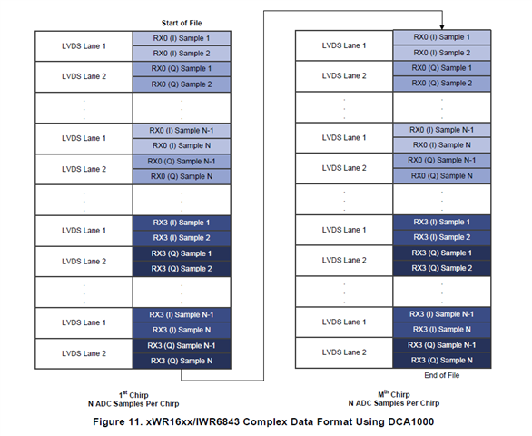
Input data rate is 600Mbps and two LVDS lanes are used 

Please let us know the timing relations between DATA, CLK and FRCLK signals.

  • Hello,

    Thank you for reaching out to Texas Instruments. Please allow us until after the weekend to respond to your query. 

    -Shareef

  • The datasheet should be able to provide the relative timing between the signals. 

    Hope this helps,

    -Shareef

  • Hi Shareef,

    Thank you for the response!

    1. From the screenshot you have shared, 1 FRCLK = 8CLK. So if CLK is 300MHz, FRCLK = 300MHz/8 = 37.5MHz. Please confirm the understanding

    2. Is FRCLK used for byte alignment?

    3. What does FRCLK high and low indicate?

    4. We use AWR6843, with 4 receiver channels, 2 lanes, complex data with 256 ADC samples each of 16 bits.

    From document Mmwave Radar Device ADC Raw Data Capture.pdf (swra581b), Figure 11,

    We understand, 

    a. "I" sample is always received from lane 1 and "Q" sample is always received from lane 2

    b. All 4 receiver channels are not active at the same time. As in, 256 samples of RX0 is first received followed by RX1, RX2 and RX3. Please confirm

    c. Also could you let us know what chirp indicates for AWR6843 and how should it be configured?


  • Any inputs on the above questions will be very useful

    Thanks in advance

  • Hello Jay,

    Apologies for the delay on this, I have am still in communication with my team on this thread. I will get back to you in a couple of days. 

    Thanks,

    -Shareef

  • Jay,

    #1 - The frame clock will be equal to the sample bit width 12/14/16 selected

    #2 - Frame clock is used to de mark the 12/14/15 bit boundaries of the ADC samples 
     
    #3 - Frame clock is used to de mark the 12/14/15 bit boundaries of the ADC samples it will be high for half and low for half of the sample bits
     
    #4 – The format is based on how the data is store in ADCBuffer (interleaved /non-interleved modes) and how the data is mapped in the CBUFF lane mapping registers. This would be difficult if starting to build the configuration from scratch
    -Shareef