This thread has been locked.

If you have a related question, please click the "Ask a related question" button in the top right corner. The newly created question will be automatically linked to this question.

FDC1004EVM: Application Inquiry

Part Number: FDC1004EVM
Other Parts Discussed in Thread: FDC1004

Hello Team,

I'm posting on behalf of my customer:

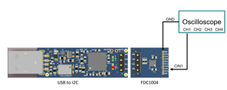
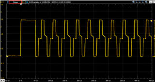
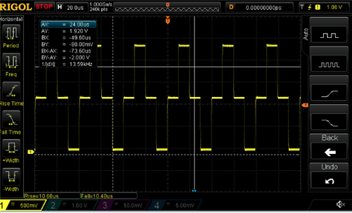
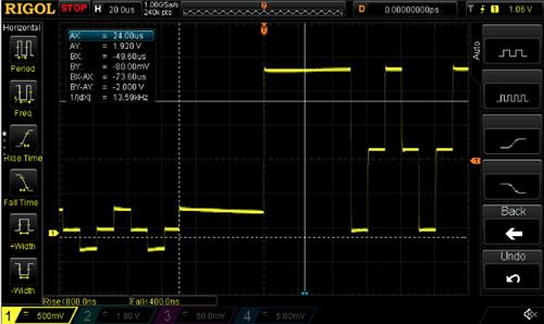
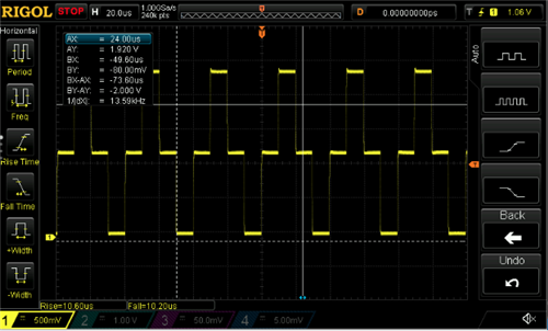
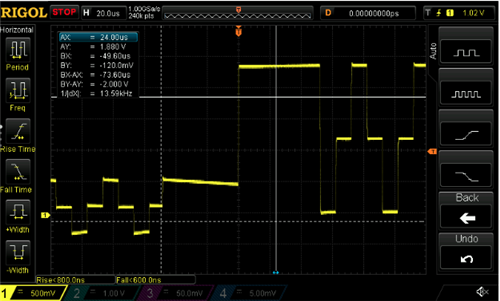
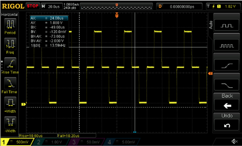
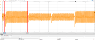
I am measuring from 3 capacitive sensors using the FDC1004EVM board. The board, however, seems to be switching between channels (i.e. sensor 1 signal is now appearing on sensor 3 channel, etc.) This has been recurring, even though I have all 3 sensor cables shielded and in twisted pairs. They are connected to Shield 1 and the settings are set for single ended measurements for the 3 sensors with CAPDAC enabled.Can someone please help me resolve this issue or tell me why this is happening?

Regards,

Renan

  • Hello Renan, 

    Is it possible to get a screenshot of the data switching between channels and share the register settings used for this? My main care about is seeing the measurement configuration registers and FDC configuration register (0x08 through 0x0C) but it may be helpful to see all registers if possible. 

    Additionally, when you say the cables are shielding and in twisted pairs, are they all next to each other? Is it a shielded wire or are the twisted pairs the CHx and SHLD1 connections? 

    Thank you, 

    Justin Beigel

  • Hello Justin.

    Please see my customer response below:

    The shielded twisted pairs are only near each other at the point of contact with the shield 1 wire as shown in the photos below. I have attached a screenshot of the registers. The switching of channel data only happens between runs, as in the data doesn’t switch in the middle of a measurement. The subsequent measurement will have swapped amplitudes between channels.

    Attachment.zip

    Regards,

    Renan

  • Hello Renan, 

    The register screenshot has the same value for all measurement configurations. Can you confirm they are using 3 different configurations for the measurements and what those are? 

    Additionally, is it possible to get the sensor waveform for a given channel for two measurements where the data switches? 

    Thank you, 

    Justin Beigel

  • Hello Justin,

    Please see my customer response below.

    It was my impression that I could configure the board and measurement settings using the configuration tab. My current settings are in the attached photo. I have also attached two plots to show an example of when the data switches. I am reading out of 3 channels. You can see that red and yellow switch amplitudes. Each of the signals are from a capacitive sensor.
    Thank you again for the help.

    Regards,

    Renan

  • Hello Renan, 

    Yes, the board can be configured from the configuration tab. Sometimes the register tab needs to be manually updated to reflect this or the register reading rate needs to be set. The last screenshot you sent was enough information about the configuration though. 

    The behavior of this looks as if the measurement configuration channels are switching before starting the next measurement. How is the customer starting and stopping the different groups of measurements? 

    Best Regards, 

    Justin 

  • Hello Justin,

    Generally my customer unplug the board and close the GUI in between each measurement. 

    Regards,
    Renan

  • Hello Renan, 

    Are they reconfiguring the device every time they repower the board? The device register settings are not persistent after the part is powered down.

    If they are reconfiguring it properly each time, can you have the customer view the sensor waveform on an oscilloscope? We will want to check that the waveform is consistent between power cycles for a given sensor. 

    Best Regards, 

    Justin Beigel

  • Hello Justin,

    Apologies for this late response, my customer just got back from vacation: Please see their response below:

    I have a question about the oscilloscope. Should I be using a function generator with a square wave input to view baseline capacitance of the sensor only? Or am I applying pressure to the capacitive sensor while connected to the function generator and oscilloscope?

    Regards,

    Renan

  • Hello Renan, 

    The oscilloscope should be connected while the device is connected to the sensor. We want to see the waveform that the FDC1004 is creating with the capacitive sensor. 

    Best Regards, 
    Justin 

  • Hello Justin,

    How do I connect the output of the board to the scope if it is an I2C bus?

    Regards,
    Renan

  • Hello Renan, 

    You don't need to connect to the I2C bus. To measure the sensor waveform, just connect the oscilloscope to the CINx pin on the EVM like so:

    Best Regards, 

    Justin Beigel

  • Hello Justin,

    Please see response from my customer:

    I recorded the oscilloscope measurements for each sensor port, as you described. I’m attached a document with the photos as well as video footage of each signal. Sensor 1 had a strange waveform that fluctuated a lot so I attached 3 photos of the 3 waveforms I could capture.

    osci_reading.zip

    Regards,


    Renan

  • Hello Renan, 

    Thank you for the information. I am still looking into this and will have more information for you by the end of the day tomorrow. 

    Best Regards, 
    Justin Beigel

  • Hello Renan, 

    The static image on the Sensor1 waveform looks good but I am not sure what is causing the fluctuated signal in the video shared. For reference, here is an example of what the waveform should look like: 

    There is a startup square wave before the oscillation begins and the device starts sampling the sensor. The startup portion of the waveform is easily seen on the oscilloscope captures in your attachment but the sampling portion is not clear from all waveforms. If you are unable to get a steady waveform on the oscilloscope, try isolating the sensors so that only one is active at a time. 

    If you are able to get a clear view of the sampling section of the waveform, it would be good to compare the waveform on a given sensor before and after the data switches between the channels to check for consistency. 

    Best Regards, 

    Justin Beigel

  • Hello Justin,

    If this is the case, does that means sensor waveforms 2 and 3 are not correct?  
    Another issue is the channel switching does not happen every time, nor do I know exactly when it occurs so I am not sure how to look at those waveforms.
    Regards,
    Renan
  • Hello Renan, 

    The waveforms shared were noisy and hard to tell if they were correct. If you are able to look at at the data without power cycling the EVM, you could just capture the channel switched waveform after the data switch has been noticed. 

    Best Regards, 

    Justin Beigel

  • Hello Justin,

    Please see response from my customer:

    I was able to get a better signal without so much fluctuation for sensor 1. Sensors 2 and 3 however consistently showed a weird shift in amplitude of the square wave. I have attached screenshots.

    Sensor1:

    Sensor2

    Sensor3

    Regards,

    Renan

  • Hello Renan,

    Justin and our other FDC expert are out today and the following week.  In the interim I will be looking into your response; however, I may need some time to understand your issue and determine a possible solution.  Will provide you an update by Monday, if not later today.

  • Hello Renan,

    I apologize for the delays here our FDC experts are still out of office and Patrick has gone on paternity leave earlier than he expected. Thanks for the waveforms, they look significantly less noisy than was shown in the video earlier and has a clear distinct startup waveform.

    Does the amplitude begin to shift slowly during the measurement? Or is there a sudden shift in amplitude?

    If the shift seems sudden then they could time the amplitude shifts to see if  this is normal. When continuous sampling is enabled on multiple channels at once the customer should see the amplitude stay high based on the sampling rate they have configured. For example if they are sampling 3 channels and using the 400 samples/s sampling rate, then they should see the channel 1 have a high amplitude for 2.5ms and remain in a lower amplitude for 5ms since they are sampling two other channels during this time.

    Based on the waveforms provided for sensor 2 and 3 it seems like the amplitudes should be fine but if the customer could change their time scale then they could confirm that they are just seeing a low amplitude while the sensor is sampling the other channels. I have attached a screenshot below this is probing channel 1 with channels 2 and 3 being sampled as well. Each of these time different section is 2.5ms.

    Best,

    Isaac

  • Hello Isaac,

    Good day and apologize for this late update, my customer was on leave in the past few weeks due to personal matters she attended. The latest response she gave me was:

    I have a clarification question in regards to the last message. Are you saying that it is normal for the recording channel to show a change in amplitude when other channels are being sampled from?

    Regards,

    Renan

  • Hello Renan, 

    Yes this is a normal behavior. When the channels are not currently being driven for the measurement, they are floating and can be impacted by the channel that is currently active. The waveforms you shared all look normal for this device. 

    Best Regards, 

    Justin Beigel