This thread has been locked.

If you have a related question, please click the "Ask a related question" button in the top right corner. The newly created question will be automatically linked to this question.

LDC1314: Production Batch - Varying measured values

Part Number: LDC1314
Other Parts Discussed in Thread: LDC1614

Hi!

We are already in serial production with sensors that utilizes LDC1314 on-board. Regarding the performance, there were no complaints so far. We already used several thousands of the chip and faced no issues. However, recently we faced issues with multiple failures during EOL testing regarding certain limit checks.

The inductance values of the coils measured by the LDC1314 was the issue. Hence, we segregated the OK and NOK sensors, measured the inductance of the coils using LCR meter, checked the BOM if there are any exchange of components etc.

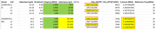
Sensor -> Sensor name

Coil -> Naming of the coil to be measured

Inductance (µH) -> Measured externally using LCR meter

Rs (ohms) -> serial resistance of the coil (measured using LCR meter)

Frequency (MHz) -> Frequency of the coil under oscillation state (measured using oscilloscope)

Inductance (µC) -> Inductance value measured by the microcontroller using the values obtained from LDC.

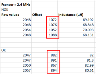
As seen from the figure above, the physical inductance, serial resistance and frequency of individual coils are pretty much comparable and within the limits. However, the inductance values calculated from the µC deviate by a considerable amount. Since the µC Firmware was the same across both the OK and NOK sensors, we checked the batch of LDC, and we found the following.


LDC1314 84U ATNT -> NOK sensors

LDC1314 13U ALEO -> OK sensors


It will be great if you can help me in finding out why such a deviation in measurement is happening, that corresponds directly to the production batch of the LDC1314. Please let me know if you require additional information.


Thanks!


  • Naveen,

    Thank you for the up front detailed description.
    We are sorry you are experiencing problems with the device.

    A few questions:

    1. Are all of the LDC1314 84U ATNT devices giving NOK results, or is it a subset?
    2. If it is a subset, can you give a number/percentage of them that are giving NOK results?
    3. It looks like the inductances from the LCR meter are about half of the uC results.
      This isn't necessarily pointing to a problem, but I am curious as to why that is.
    4. Are you using the same uC to measure the different sensors, or does each LDC/sensor have its own uC?
      Is it possible the NOK sensors are using different LDC devcie settings?
    5. When you monitor the sensor signals with an oscilloscope, are you using a high impedance, low capacitance probe?
      We have found that using a series 1k resistor between the probe tip and the test point can really reduce parasitic loading compared to using only the  Hi-Z probe.
    6. Can you monitor and compare the value of the reported uC inductance before and during the o-scope probe of the sensor?
      If you can, does the reported uC inductance change?
    7. What is the total capacitance of the sensor? Is it possible that a shift in the sensor capacitance is causing the NOK results?
    8. The Rs of the NOK sensor is a smidge higher (~0.1Ω) than the OK sensors.
      You may have tried this already, but can the LDCs of an OK sensor and a NOK sensor be swapped just to confirm the issue follows the device?

    Apologies for going overboard on the questions, but we are assuming this is an urgent matter, and that an ASAP solution is needed.

    Regards,
    John

  • Hi John!

    Thanks for the quick response. I am recording my answers below, adjacent to your questions.

    1. Are all of the LDC1314 84U ATNT devices giving NOK results, or is it a subset?
      1. All of the LDC1314 84U ATNT devices are giving NOK results.
    2. If it is a subset, can you give a number/percentage of them that are giving NOK results?
      1. See answer for Q1.
    3. It looks like the inductances from the LCR meter are about half of the uC results.
      This isn't necessarily pointing to a problem, but I am curious as to why that is.
      1. This is due to an internal calculation error due to a linear offset. This is now rectified but is still present in our Firmware that was flashed on these sensors. For our measurement principle, this did not pose a risk.
    4. Are you using the same uC to measure the different sensors, or does each LDC/sensor have its own uC?
      Is it possible the NOK sensors are using different LDC devcie settings?
      1. Every Sensor (sensor PCB) has a uC and a LDC on-board. The uC is the same across all the sensors and the LDC1314 is populated on all these sensors. All the uCs are having the same firmware in it, and we do have checks for configuration settings of LDC. Hence, it is not possible that the settings would have changed between the sensors.
    5. When you monitor the sensor signals with an oscilloscope, are you using a high impedance, low capacitance probe?
      We have found that using a series 1k resistor between the probe tip and the test point can really reduce parasitic loading compared to using only the  Hi-Z probe.
      1. Yes. It is a high impedance, low capacitance probe. However, the measurement with oscilloscope was not done simultaneously with the ones with LDC (values from uC). Hence, I am pretty positive that the measurements were not affected by one another.
    6. Can you monitor and compare the value of the reported uC inductance before and during the o-scope probe of the sensor?
      If you can, does the reported uC inductance change?
      1. There was no considerable change in inductance observed. In addition to that, the sensor was powered OFF and ON multiple times, to make sure that the value is considerably stable.
    7. What is the total capacitance of the sensor? Is it possible that a shift in the sensor capacitance is causing the NOK results?
      1. The total (tank) capacitance of the sensor is 78 pF. We are using capacitors from NP0 series with 2% tolerance. Hence, this could not have resulted in the shift we are observing. Moreover, I tried to remove the capacitors and populate them with some newer ones (NP0 dielectric) from the lab but the results were still the same.
    8. The Rs of the NOK sensor is a smidge higher (~0.1Ω) than the OK sensors.
      You may have tried this already, but can the LDCs of an OK sensor and a NOK sensor be swapped just to confirm the issue follows the device?
      1. This test is currently underway at our supplier. I will forward the response as soon as we have something on this. But regarding the change in resistance -> The change was expected one and was observed even across the OK sensors.
        1. The LDC from an OK sensor was exchanged with the LDC from an NOK sensor, and the problem moves along with the LDC. Hence, it is clear that the problem does not lie with the PCB/µC/other components on PCB. The tests were conducted at our supplier side.

    Here is another interesting observation from the LDC. We are currently making use of the output gain feature, which allows us to read 16-bit value (ENOB). For the same purpose, we are also using the offset feature. However, I noticed that there was a considerable shift in the offset, although the change was not observed in this 16-bit value.

    Formula used -> 

    FIN_DIVIDER - 1

    OUTPUT GAIN - 4 (16-bit value)

    Reference Frequency is considered as 20 MHz (clock divider of 2 was used on source of 40 MHz). The datasheet specifies a mid value of 43.4. However, for computation purpose, we assumed it to be 40 MHz.

    We are currently making use of the internal clock of LDC1314 as reference frequency. Could this be the source of such an offset?

    Highly appreciate your help! Thanks!

    Best Regards,
    Naveen.

  • Naveen,

    Thanks for the reply and the add'l information.
    The LDC1314 internal clock should have good enough specs to not contribute to or cause what you are seeing.
    But since we are still working in "detective" mode, let me suggest another experiment.
    Do you have an accurate, stable clock source that will support the Reference Clock specs in the data sheet, and provide the same frequency you are using for the internal clock?
    If so, can you try running an OK sensor and an NOK sensor from the internal & external clocks ?

    Regards,
    John

  • Hi John,

    Currently, we do not have such a stable clock source that could support the specs of the LDC. The only source that I could think of is from the uC, where I could output 36 MHz. However, the routing of clock output from the uC to the LDC will be an issue, which will be difficult from our end. Its accuracy is also in question and has never been tested so far. I have to discuss internally regarding conducting such test.

    Is there a way that the TI can support in such a task, since the internal structure is well known to the TI (and not to us)? (If we can ship some samples from NOK sensors and OK sensors)

    Here is another interesting observation. The NOK sensors have a consistent shift from the OK sensors (in terms of inductance values measured by LDC).

    The values on the left side of yellow mark are from OK sensors (within the Maximum and Minimum Limit) and those on the right side are from NOK sensors (all are below the minimum limit). However, if you notice, the deviation in the values are comparable between OK and NOK sensors. This looks like some constant shift within the LDC but not sure where it comes from. This also aligns with the low offset values that I mentioned earlier.

    Regards,

    Naveen.

  • Naveen,

    This sounds like an issue with the device settings.
    Would it be possible to compare the register settings between an OK and NOK device?

    Regards,
    John

  • Hi John,

    The settings for the LDC on both OK and NOK sensors are the same. As I have stated already, the firmware used on OK and NOK sensors are one and the same. On top of that, there is a specific function present in the FW that crosschecks the settings written to the LDC (Configuration is first written to the LDC and then the registers are read back and compared with the written values).

    Is it possible that the register settings changes after it is written to the LDC?

    Regards,

    Naveen.

  • Naveen,

    I don't recall ever hearing about register problems like you describe. I will have other members our our team review your findings and will update this thread by COB on Wednesday.

    Regards,
    John

  • Hi John,

    Thanks for the info. It was just as assumption but I did not see any behaviour in OK/NOK sensors. The register settings are the same.

    The constant shift in measured values seems to be coming from the hardware and not software settings. At least it seems for me.

    Thanks again! I will wait for further updates.

    Edit - The LDC from an OK sensor was exchanged with the LDC from an NOK sensor, and the problem moves along with the LDC. Hence, it is clear that the problem does not lie with the PCB/µC/other components on PCB. I updated the same to the response I gave earlier (8 questions).

    Regards,

    Naveen.

  • Naveen,

    Would it be possible to measure the self-resonant frequency of your sense coil?
    This would be for the coil by itself, without any additional board-level capacitance.

    Regards,
    John

  • Hi John,

    The self-resonant frequency of the sensing coils are around 4 MHz. The only difference is that the waveform looks bad and distorted without any external caps.

    Regards,
    Naveen.

  • Thanks Naveen.

    The guidance we offer is for the nominal sensor frequency (w/PCB cap) to be less than 80% of the coil's self-resonant frequency (SRF, w/o PCB cap, only parasitic capacitance):

    fsensor ≤ 0.8*SRF

    The coil acts like an inductor when fsensor < SRF, but it acts like a capacitor for fsensor > SRF. 
    When fsensor ≈ SRF, then the sensor ideally acts like a resistor, with no capacitance or inductance.
    In reality random tolerances or fluctuations will cause the coil to look like a capacitive or inductive reactance. 
    If you work thru the s-plane expressions fr the equivalent impedance of the LC tank circuit, you can see the impedance of the coil when slightly below self-resonance can look like a much larger inductor (than it physically is), and that the effective inductance can vary a lot with just a small change in frequency. 

    It sounds like what could be happening is your sensor frequency is about the same - or very close - to the coil's self-resonant frequency and some slight device variations - perhaps in the LDC analog circuits - is showing up as an inductance shift or offset.

    The way to confirm or disprove this would be to use a larger PCB cap for your sensor to lower the fsensor to less than 80% of the SRF and see if the OK and NOK devices give more similar readings. Note that you will most likely have to change some of the LDC device settings to accommodate the lower fsensor for this experiment.

    Regards,
    John

  • Hi John,

    Thanks for this brief explanation regarding why such deviation in our inductance measurement might be happening. As I have already noted in my initial description about the issue, we are already in serial production and have been using the LDC1314 since two years now. This is the first time we have noticed such a deviation in the measured value. My questions are the following.

    1. Why there is a slight device variation (perhaps in LDC analog circuits) now with this batch (LDC1314 84U ATNT) and not in the previous batches (> 2 years since we started testing). Such variation was also not observed in LDC1614, which we were using since 2017.

    2. Can we trust that the variation in the device will not go further, resulting in much deviated measured value? How can we ensure that from our side? This is extremely important since we are in serial production, and could not make a change that easily with the HW/FW. 

    I appreciate your help in this regard but currently the production is halted because of this issue. If the TI says that the variation will stay as it is (like an offset), then we can go ahead with using the chips from this batch. Otherwise, we should think about other solution.

    Thanks again!

    Regards,

    Naveen.

  • Naveen,

    The key consideration is to know how the LDC interacts with the rest of your design.
    Until we understand that better, it will be difficult to figure out the root cause of what you are seeing.

    My guess is that if there was a defect, you would be seeing more symptoms than just a shift in the inductance. 
    So based on what we have discussed so far, I think we can assume the latest devices are okay, and that they simply have an offset in your design.

    Since we don't have a root cause for what you are seeing, we can't say there won't be more variations.
    If problems get worse to the point that you can't build and ship products, you will need to take a step back and more fully understand the device specs and how they impact the behavior of your design.
    We have an extensive Inductive Sensing FAQ,  Inductive Sensing Blogs was well as app notes and training videos that can help with this.

    Please let me know if you have any more questions.

    Regards,
    John

  • Hi John,

    Thanks for the response. I will proceed with the tests you suggested and see if this is indeed the issue. Hopefully, by tomorrow itself.

    Regards,

    Naveen.

  • Hi John,

    I performed a test by changing the sensor frequency from 4 MHz to 2.4 MHz, by including bigger caps in the circuit.

    This was the inductance reading from OK batch ->


    This was from NOK batch -> 

    Note -> inductance calculation was not changed in FW, and hence the large values.

    The offset in measured values is still visible. Here is the raw measurement values and the offset configured for every channel, with corresponding inductance calculated.

    This clearly indicates an offset, which is not affected by the sensor frequency. It will be great if you can help me discover the source of this issue! Thanks!

    Regards,

    Naveen.

  • Naveen,

    In your most recent reply, how are the Raw values and Offset related?

    Regards,
    John

  • Hi John, 

    The raw values are set in such a way that they are closer to 0x7FF. The offset is recalculated and the LDC is configured with this offset (unique for each channel), until we reach the measured value close to 0x7FF. Then, the actual value is calculated according to the formula specified in the datasheet .

    It was the same as the previous measurements I did, with fsensor as 4 MHz. 

    Regards,

    Naveen.

  • Naveen,

    Would you please provide the detailed sequence & steps you outlined in your last reply, including the starting values for any parameters?

    Regards,
    John

  • Hi John,

    It has to be noted that the procedure has not been changed and only the capacitance on the coil side was changed to bring the 4.0 MHz coil frequency to 2.4 MHz. The settings remain the same, since there was no major drawback noticed. Nevertheless, I am describing the steps below, by means of flowchart.

    As seen in the flowchart above, after the initial configuration of the parameters (apart from output gain) using Multi_Channel_Config function, the Output-Gain configuration is done (using RESET register, as specified in the datasheet). In order to have a much effective measurement range, the offset is set in a way that the measured value varies around 0x7FF. For this, a special function called LDC_Offset_Detection is used, whose flowchart is provided below.

    As seen in the flowchart above, all the coils are individually measured at first, and then using the LDC_offset_recalculation() function, the proper offset is determined (using the formula from the datasheet), to obtain a measurement value around 0x7FF. The actual FW code used is given below as a screenshot. 

    Once it has been determined that the offset is good enough, to obtain a measurement value around 0x7FF, the new offset is configured individually for all the channels, and the normal measurement run is started.

    Regards,

    Naveen.

  • Naveen,

    Thank you for the details. I will review the info you have provided and update the thread by COB tomorrow.

    Regards,
    John

  • Naveen,

    I am still reviewing the  latest info you provided. There are no questions or updates at the moment and I will provide an update by Wednesday of next week.
    In the interim, I will send you an E2E friend request. Please accept it and we can resume our conversation via private messages then.
    Regards,
    John

  • Hi John,

    Sure. Thanks for the update!

    Regards,

    Naveen.