


Hi
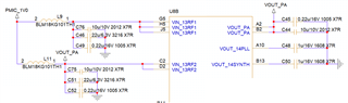
I designed the RF power line as follows.
However, ripple occurs in the RF power line every transmission cycle as shown in the figure below.
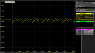
What causes it?
Hi
I designed the RF power line as follows.
However, ripple occurs in the RF power line every transmission cycle as shown in the figure below.
What causes it?
