This thread has been locked.

If you have a related question, please click the "Ask a related question" button in the top right corner. The newly created question will be automatically linked to this question.

AWR2243: The problem of azimuth and elevation angle acquisition and 3D drawing

Part Number: AWR2243

Dear TI,

       I use AWR2243 four chip cascade board (RF-EVM+DSP-EVM) and Ti's matlab program (4chip_cascade_MIMO_example). I have questions about obtaining target azimuth angle and elevation angle in matlab.

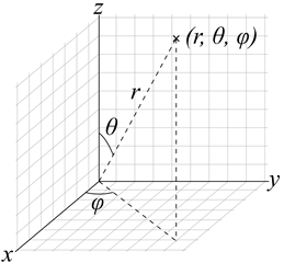
In matalb program, the results of direction-dimension FFT and pitch-FFT are directly used as the azimuth angle and elevation angle pitch of the target,as shown in Figure 1:

figure 1

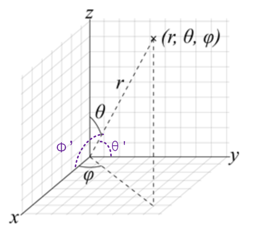
Then, the target is drawn in 3D through coordinate transformation, as shown in figure 2

figure2

My question is:

In the array geometric relationship, there is a difference between the true azimuth (elevation ) angle of the target and the included angle of the x-axis (y-axis), as shown in figure 3

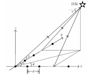
figure 3 An example。

Why is this relationship ignored in the process of angle calculation in MATLAB?

Why can we directly use the angle obtained by two FFTs, ignoring the coupling relationship between them?

  • Hi Bo,

    Consider a vector in 3D space as shown below. We obtain measures of φ and θ using the angle FFT on the azimuth plane and elevation plane respectively (figure 1). This measure of (r, θ, φ) should suffice to get its respective cartesian (x, y, z) point representation. The same has been done in figure 2.

    Figure 3 - Can you explain the coupling you are referring to by drawing over the image I have included?

    Regards,

    Kaushik

  • Hi Kaushik,  

        In Figure (a), we draw two new angles φ‘ and θ’, which represent the angle between the target's incoming ray and the x-axis antenna and the y-axis antenna.

       My question is: Why do we obtain measures of φ and θ instead of  φ‘ and θ’ using the angle FFT on the azimuth plane and elevation plane respectively.


    Figure(a)

    Regards,

  • Hi Bo,

    The measures of Phase Differences across Tx-Rx combination will be in the plane in which the antennae are arranged (generally azimuth and/or elevation). Appropriate samples w.r.t antenna combination are picked so that we can measure  φ and θ instead of 'φ‘ and θ’. I would recommend you go through the following document (section 2 and 3) for a better understanding.

    https://www.ti.com/lit/an/swra554a/swra554a.pdf

    Regards,

    Kaushik