This thread has been locked.

If you have a related question, please click the "Ask a related question" button in the top right corner. The newly created question will be automatically linked to this question.

AWR1843: uniflash: Sending Erase command to device…..

Genius 13655 points
Part Number: AWR1843
Other Parts Discussed in Thread: UNIFLASH,

Hello Champs,

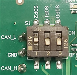
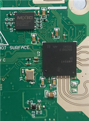
Customer made their own board according to the xWR1843BOOST Design Database and Layout Details  RevD which is the same to TI AWR1843BOOST.

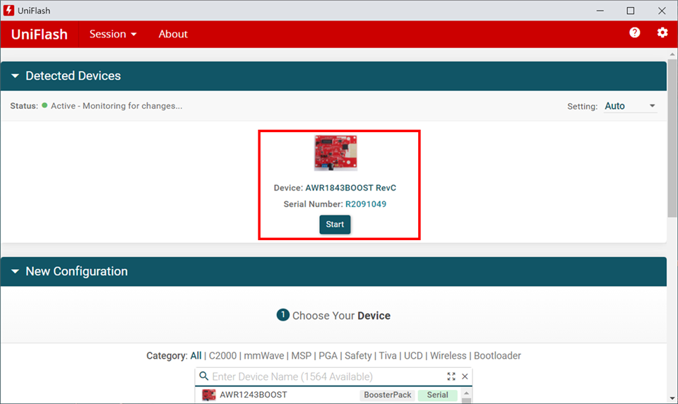
He can use uniflash to program AWR1843BOOST. But he failed to program his own board. It stuck at Sending Erase command to device…..

Below are the steps.

Win10

5V/3A

 uniflash_8.0.0

 ti\mmwave_automotive_toolbox_3_4_0\labs\lab0008_automated_parking\prebuilt_binaries\pa_18xx_mss_demo.bin


Uniflash stuck at Sending Erase command to device…..


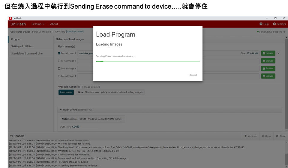
[2022/10/6 下午3:17:08] [INFO] Cortex_R4_0: Initialization complete.
[2022/10/6 下午3:17:08] [INFO] Cortex_R4_0: Flashing process starting...
[2022/10/6 下午3:17:08] [INFO] Cortex_R4_0: Connecting to COM Port COM9...
[2022/10/6 下午3:17:08] [INFO] Cortex_R4_0: Reset connection to device
[2022/10/6 下午3:17:09] [INFO] Cortex_R4_0: Set break signal
[2022/10/6 下午3:17:09] [INFO] Cortex_R4_0: Connection to COM port succeeded. Flashing can proceed.
[2022/10/6 下午3:17:09] [INFO] Cortex_R4_0: Reading device version info...
[2022/10/6 下午3:17:09] [INFO] Cortex_R4_0: ** 1 files specified for flashing.
[2022/10/6 下午3:17:09] [INFO] Cortex_R4_0: Checking file C:/ti/mmwave_automotive_toolbox_3_4_0/labs/lab0009_multi-gesture-16xx/prebuilt_binaries/xwr16xx_gesture_ti_design_lab.bin for correct header for AWR1843.
[2022/10/6 下午3:17:09] [INFO] Cortex_R4_0: AWR1843 device, fileType=META_IMAGE1 detected -> OK
[2022/10/6 下午3:17:09] [INFO] Cortex_R4_0: !! Files are valid for AWR1843.
[2022/10/6 下午3:17:09] [INFO] Cortex_R4_0: Format on download was specified. Formatting SFLASH storage...
[2022/10/6 下午3:17:09] [INFO] Cortex_R4_0: -->Erasing storage [SFLASH]
[2022/10/6 下午3:17:09] [INFO] Cortex_R4_0: -->Sending Erase command to device...


Thanks.
Rgds
Shine

  • Hi,

    Unfortunately we don't have sufficient information to provide assistance.

    Customer must debug the custom board and make sure it is functional

    Based on the log it seems that the UART communication with the board is not working.

    thank you

    Cesar

  • Hi,

    At present, I feel that there is a problem with the FLASH circuit. If I want to compare the FLASH signal of TI's development version and my development version, I can measure those pins. Is there any relevant instructions?

    thank you

    Wendy

  • Hi,

    If you have an AWR1843BOOST board from TI, you can use that board as a reference.

    You should also consult the Flash Manufacturer data sheet.

    As you already know, we provide the AWR1843BOOST schematics on the EVM website

    Thank you

    Cesar

  • Hello Wendy,

    Did you use a different flash variant compared to the AWR1843BOOST? 

    Did you check to see if the radar is waking up properly? First, put the device into development mode (SOP0 and SOP1 closed). If you probe the XTAL_P pin of the device you should see the 40MHz signal. If you probe the VBGAP pin you should see 0.9V.

    Regards,

    Adrian

  • Hello Adrian,

    A:Did you check to see if the radar is waking up properly? First, put the device into development mode (SOP0 and SOP1 closed).B

    B:Measurement photo:

    A:If you probe the XTAL_P pin of the device you should see the 40MHz signal.

    B:Measurement photo:

    A:If you probe the VBGAP pin you should see 0.9V.

    B:Measurement photo:

    A:Did you use a different flash variant compared to the AWR1843BOOST? 

    B:I suspect it's a flash variant issue, but comparing the two should make no difference.

    thank you

    Wendy

  • Hello Wendy,

    It looks like the radar is waking up properly, so I do not expect any issues on the radar side.

    It seems like the flash should meet the requirements of the bootloader so I expect it should work. Can you share the schematic connections between the flash and the radar and confirm that all of the correct pullups are connected?

    Since you have access to an AWR1843BOOST, is it possible to try to swap the flash part from the AWR1843BOOST onto the custom board and see if it works? This would help confirm if it is an issue with this specific flash variant.

    Regards,

    Adrian

  • Also, in addition to above, can you confirm if the customer has programmed the XDS110 firmware on the custom board?

    This should be done according to the instructions in the below thread:

    https://e2e.ti.com/support/sensors-group/sensors/f/sensors-forum/827266/awr1642-custom-board-is-not-detected-by-usb-comm-port/3060977#3060977

    Regards,

    Adrian

  • Hello Adrian,

    A:Also, in addition to above, can you confirm if the customer has programmed the XDS110 firmware on the custom board?

    B:I have performed the XDS110 firmware steps on a custom board.

    A:It seems like the flash should meet the requirements of the bootloader so I expect it should work. Can you share the schematic connections between the flash and the radar and confirm that all of the correct pullups are connected?

    B:I measured the signal of the circuit near the Flash, and there is a difference compared with the TI board. After replacing the resistor, the Flash can be programmed normally.

    Thank you for your inquiry and reply.

    Wendy