This thread has been locked.

If you have a related question, please click the "Ask a related question" button in the top right corner. The newly created question will be automatically linked to this question.

AWR1642BOOST: Development mode(Sop 0 and Sop 1 closed, Sop 2 open) showing hardware error(NERR_OUT)

Part Number: AWR1642BOOST
Other Parts Discussed in Thread: UNIFLASH, AWR1642, IWR1443BOOST

Hi,

The errors listed below, as well as my efforts to correct them, were unsuccessful.

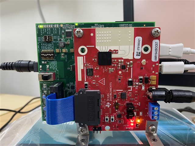
I purchased an EVM AWR1642BOOST and DCA1000 and attempted to acquire data using the DCA1000 training video.

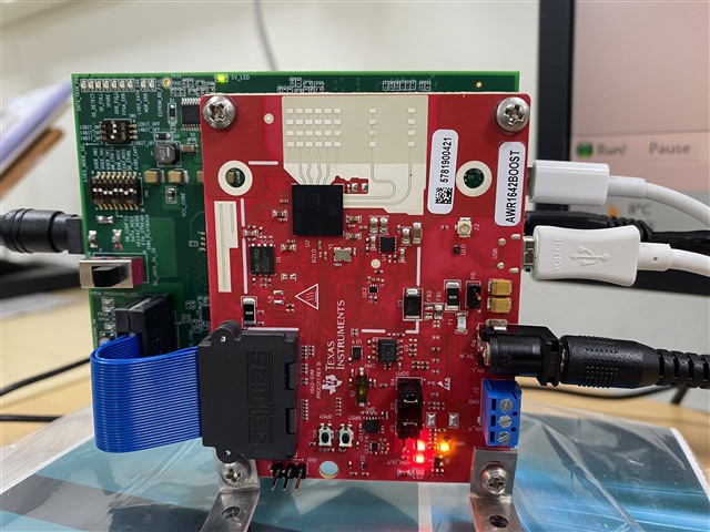
  1. While in development mode(SOP 0, SOP1 closed, and SOP 2 open), I ran into a hardware fault (the NERR OUT led is red just after supplying power to EVM).
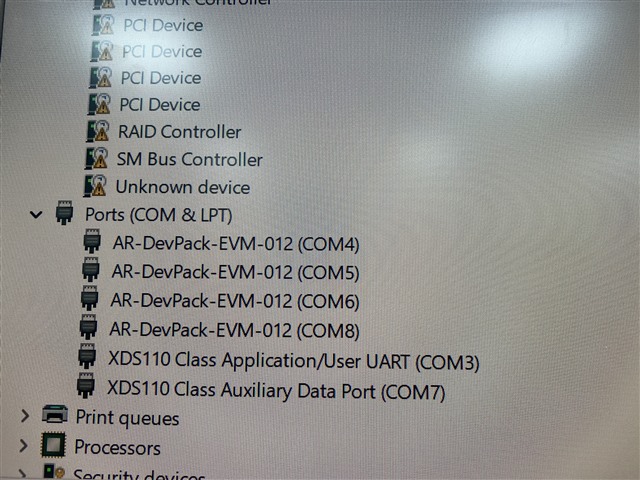
  2. I carried out the current hardware error. When I clicked the SPI Connect button in mmWave Studio, I found NERR OUT was off.
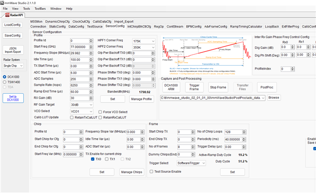
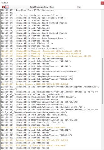
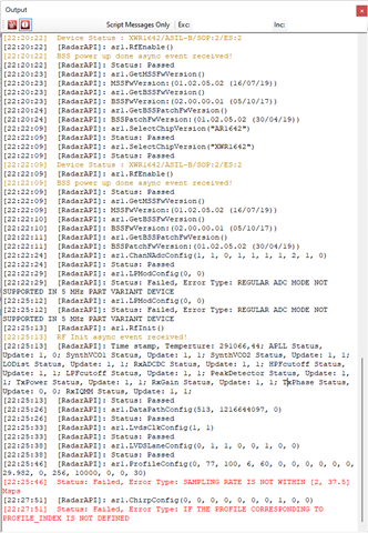
  3. Then I get the following problem in StaticConfig when selecting Regular ADC mode in LP Mode: [22:22:29] [RadarAPI]: Status: Failed, Error Type: REGULAR ADC MODE NOT SUPPORTED IN 5 MHz PART VARIANT DEVICE

I disconnected the DCA1000 and used the device's out-of-the-box demo to make sure the EVM was operating flawlessly. The default demo ran successfully.

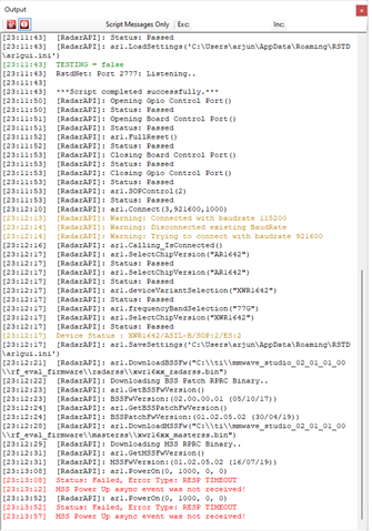
Finally, I wiped the previous flash (SOP 0, SOP 2 closed, and SOP 1 open) with Uniflash and attempted to flash the BSS and MSS anew with mmWaveStudio. But I made the same error.

The NERR OUT led turns red when power is applied.

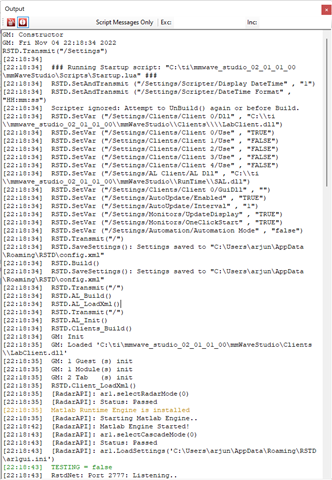
Please examine the pictures below and provide a solution.


Regards

Arjun

  • Hello,

    The errors you are seeing are due to incorrect configuration, not due to a hardware issue. First, you need to set the ADC to low power ADC mode. For AWR1642 only low power ADC mode is supported.

    Second, the max sampling rate is 6.25Msps for complex 1x mode. You are trying to set 10Msps. You need to reduce the sampling rate to 6.25Msps for complex 1x.

    If you fix the above issues this should resolve the errors you are seeing.

    Regards,

    Adrian

  • Hello Aozer,

    I really appreciate your suggestion. Tomorrow I'll set it up and get back to you.

    I have two different EVM models, the IWr1443BOOST and the AWR1642BOOST.

    1. Could you please let me know whether the raw data for IWR1443BOOST and AWR1642BOOST are the same or different?

    I would utilize a DCA1000 to record the EVMs' raw data.

    Regards

    Arjun

  • Hi Aozer,

    I followed your suggestion but I failed to set DCA1000. I have been getting errors at reading FPGA Version. Please see the below screenshots and suggestions.

    Regards

    Arjun

  • Hello,

    The error means that the DCA1000 is not connecting properly, so now it seems like the issues with the sensor configuration are resolved. Can you try following the steps in the below video to connect the DCA1000?

    https://training.ti.com/dca1000-training-video

    You need to make sure you are properly setting up your IP address or it will not connect. In some cases, if your PC has a firewall it can also cause issues, so you should disable any firewalls when using the DCA1000.

    Regards,

    Adrian

  • Hi Aozer,

    I have been following the DCA1000 training video shared by you.

    I noticed these issues:

    1. The NERR OUT led is read immediately after power is applied and turned off when the SPI connect button is pressed.
    2. When power is applied, the NERR OUT led is off, but it turns red when the MSS FW is loaded.
    3. The NERR_OUT led stays red.

    Please see the images of the EVM as well as the current and previously shared screenshots.


    I believe a hardware error is present in the device.

    Let me know if you want me to send you a video recording.

    Regards

    Arjun

  • Hi Aozer,

    I have been waiting for your response. Could you please respond to my above queries?

    Regards

    Arjun

  • Hello Arjun,

    Very sorry for the delay, there have been many escalations over the past few weeks that I had to prioritize.

    Can you follow the steps in the below link to initiate a return based on where you purchased?

    https://www.ti.com/support-quality/additional-information/customer-returns.html?keyMatch=CUSTOMER%20RETURNS

    In the mean time, before you were able to do the RF power on without the response timeout. Now, you are seeing a response timeout at RF Power on. If you power cycle both boards does this same error always occur? 

    Also, the error you were previously seeing with the DCA1000 FPGA version is not related to the NERROR. Even if you receive a new board you will still see this issue. Can you share a sceenshot of how you are configuring your IP address? 

    Regards,

    Adrian

  • Hi Aozer,

    As a researcher, I do not have time to wait long. I sorted out the issues myself very early. 

    I created a thread for a different issue: e2e.ti.com/.../awr1642boost-how-to-calculate-the-timestamps-of-each-samples

    Could you please answer, if possible?

    Regards

    Arjun