Hi all
When i read the document < TI mmWave Radar sensor RF PCB Design, Manufacturing and Validation Guide>,
I see this words
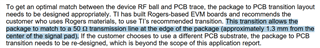
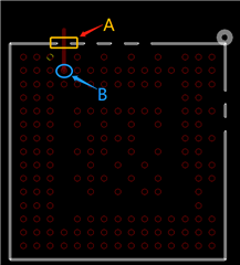
Does this means if i copy the line width and space of TI DEMO board, then i can get 50 ohm termination?
In other words, i should be use A/B line for the chip but not any 50ohm termination line.
Then i can get the 50ohm termination at the end of the chip packdge?
Does it is correct?
Thanks