This thread has been locked.

If you have a related question, please click the "Ask a related question" button in the top right corner. The newly created question will be automatically linked to this question.

MMWCAS-RF-EVM: About the antenna of MMWCAS-RF-EVM

Part Number: MMWCAS-RF-EVM
Other Parts Discussed in Thread: AWR2243,

We have started a new design based on AWR2243 cascade. Here is a question for you to confirm.


The MMWCAS-RF-EVM user guide (swru553a) roughly introduces the design method and performance parameters of the on-board antenna. We want to conduct further development based on this antenna to meet our product requirements. So can I get the HFSS or ADS simulation model of this antenna?


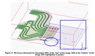
In addition, what is the reason for this strange light purple area in the simulation diagram shown in the document? Why is this area so much larger than the antenna area? Why is a semicircular area hollowed out in this area?

Thanks o lot.

Chenhui

11/05/22

  • Hi,

                Typically customers create their own HFSS model from the layout (on ti.com). I would recommend you try that and let us know in case you face any issues with that.

    The purple section is the mark open clear area around the antennas present on the board. You can ignore the semicircular area cutout shown as it is not in the FINAL board.

    Regards

  • Thank you for your reply. There is another question that needs your help to confirm.

    Usually, when we do antenna simulation, the model generally only includes the antenna, not the PCB trace from the chip to the antenna.

    The simulation model in the above figure obviously includes PCB trace. Why?

  • Hi,

           There are various sections SIMs which can be or should be done. Consider this as an example. For the Antenna alone SIMs, you may decide not to keep RF traces.

    Regards

  • Thank you for your reply. I agree with what you said. The reason for this question is that the manual (swru553a) gives Figure 18~Figure 22 and Figure 24 of the antenna simulation results, and Figure 17 (the figure I posted above) in the same document. So can it be considered that the antenna pattern simulation results in this manual take into account the influence of PCB routing(from chip to antenna)?   Actually, I just want to know this clearly.  Because usually the simulation operation of the antenna and the pattern are given without considering the pcb routing.

  • Hi,

       Yes the RF traces are included in the Antenna SIMs.

    Regards