This thread has been locked.

If you have a related question, please click the "Ask a related question" button in the top right corner. The newly created question will be automatically linked to this question.

MMWCAS-RF-EVM: Advanced frame configuration for multimode of cascaded radar

Part Number: MMWCAS-RF-EVM
Other Parts Discussed in Thread: AWR2243BOOST, DCA1000EVM, AWR2243

Hello,

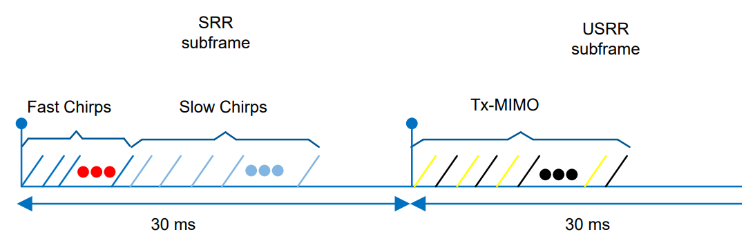
I have a question on multimode configuration for cascaded radar like page 7 of Short Range Radar Reference Design Using AWR1642

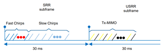
In my case, I want 2 sub-frames, for the first sub-frame 1 TX and 16 RX antennas will be used with 32 chirps, for the second sub-frame 12 TX and 16 RX antennas will used in TX-MIMO with nchirp_loop equals to 32. 

My question is where can I find example of such configuration for Lua files? Any suggestions? I understand there is a TX-beamforming example with advanced chirp configuration. However, it does not apply to my case. 

Thank you very much for the help!

Best,

Hang

  • Hello,

    I am wondering whether I could get some hints on above question?

    Thanks a lot!

    Best,

    Hang

  • Hi,

       The scripts folder in the studio installed folder has an example on the same. You will have to update the  parameters in the called API.

    ar1.AdvanceFrameConfig.

    Regards

  • Hi Abhed,

    I am assuming you were referring to this folder C:\ti\mmwave_studio_03_00_00_14\mmWaveStudio\Scripts.

    I am looking for the script for the chirp design similar as below. Could you point me which script you were referring to for the cascaded radar?

    Thank you very much for the help!

    Best,

    Hang

  • Hi,

         Yes.

    I was referring to the Advanced_Chirp_Example.lua. This example is for the Single Chip but can be edited for cascade also.

    Regards

  • Hi Abhed,

    Thank you very much! I was trying to run this LUA script (Advanced_Chirp_Example.lua) with a AWR2243Boost and DCA1000EVM as below.

    However, I always failed to capture the raw data with the given Advanced_Chirp_Example.lua script. From the log, I could successfully load the firmware and run. However, it always failed to capture the data. Do you have similar experience? I feel some chirp configuration might be wrong.

    I also tried to capture raw data with a simple MIMO LUA file. I can successfully capture the data. That's why I feel some configuration of Advanced_Chirp_Example.lua might be wrong. 

    I attached my MIMO LUA file and Advanced_Chirp_Example.lua file. 

    Advanced_Chirp_Example.zip

    AWR2243_MIMO_3TX_test.zip

    Could you help me confirm that whether you can successfully capture raw data with Advanced_Chirp_Example.lua?

    Thanks a lot!

    Best,

    Hang

  • Hi,

        Seems you have commented the capture path. Hence when you might have issued the ARM of DCA the capture path was not correctly configured the ARM did not happen correctly.

    Regards

  • Hi Abhed, 

    NO, actually, I made the capture path and firmware path easier as below. 

    adc_data_path = "C:\\ti\\mmwave_studio_03_00_00_14\\mmWaveStudio\\PostProc\\adc_data.bin"
    BSS_FW = "C:\\ti\\mmwave_studio_03_00_00_14\\rf_eval_firmware\\AWR2243_ES1_1\\radarss\\xwr22xx_radarss.bin"
    MSS_FW = "C:\\ti\\mmwave_studio_03_00_00_14\\rf_eval_firmware\\AWR2243_ES1_1\\masterss\\xwr22xx_masterss.bin"

    Have you tried the given Advanced_Chirp_Example.lua? I really doubt  something was wrong with the chirp configuration so that it could not capture the frames. The MIMO script I provided worked really well. 

    Thank you very much for the help!

    Best,

    Hang

  • Hi,

             Can you then comment out the capture API from the script for debug, and try the manual ARM of DCA and capture?

    Regards

  • Hi Abhed, 

    It still didn't work. Whenever I click the "Trigger Frame" button, it gave the error of "Status: Failed, Error Type: RESP TIMEOUT".

    I still think something was wrong with this advance frame configuration. 

    I attached the LUA file I used.

    4150.Advanced_Chirp_Example.zip

    Here are my detailed steps. 

    (1) I used the LUA file to configure the AWR2243Boost and DCA1000EVM. There was no problem. 

    (2) Then, I switched to the SensorConfig Tab.

    (3) I first clicked the DCA1000 ARM button. There was no problem. However, every time I clicked the "Trigger Frame" button, it gave the error of "Status: Failed, Error Type: RESP TIMEOUT" as below. 

    (4) There was no problem with the DCA1000EVM connection to the computer. As I previously tested that the MIMO configuration LUA file worked well. 


    Any suggestions? 

    Thanks!

    Best,

    Hang

  • Hi Hang,

                    After you comment out the capture API call, just before the manual trigger try re-issuing the Advance Frame API and see if it issues an error. If it does then try to match the values being sent in the API. For example, The current API send 40Ksps, try to reduce it to 25Ksps and check.

    Regards

  • Hi Abhed,

    What do you mean by saying "re-issuing the Advance Frame API"? Use a separate LUA file to "re-issuing the Advance Frame API"? Could you let me know which part of the LUA file I should use in order to "re-issuing the Advance Frame API"?

    Yes, the current ADC sampling rate is 40Ksps. However, if I changed it to 25Ksps, does it mean I also changed the chirp configuration?

    Thank you very much for the help!

    Best,

    Hang

  • Hi,

          I was referring to the "ar1.AdvanceFrameConfig" API. This is just before the capture configuration.

    Yes, you will have to. The updated corresponding values you can take from Studio tab of sensor config.

    Regards

  • Hi Abhed,

    It still didn't work. I feel the chirp or frame configuration in the given lua file was not workable.

    (1) I loaded the Advanced_Chirp_Example.lua file and then re-issuing the Advance Frame API. No error occurred.

    However, when I clicked "Trigger Frame" button, it gave the error of "Status: Failed, Error Type: RESP TIMEOUT".

    (2) I also tried to change the sampling rate. No error for during configuration. However, when I clicked the "Trigger Frame" button, the mmWave studio seemed freezed and after a while it showed me "Error: The number of files captured is zero!"

    I feel the chirp or frame configuration in the given Advanced_Chirp_Example.lua was wrong. 

    Did anyone use the Advanced_Chirp_Example.lua file to successfully collect the data?

    Or do you have a workable lua file or configuration?

    This issue has bothered me several days.

    I used the exact device the lua file suggested. AWR2243Boost and DCA1000EVM.

    Thanks for the help!

    Best,

    Hang

  • Hi Abhed,

    Based on your suggestions, I tried it since last Thursday (see last post). It still did not work. 

    Any suggestions?

    Thank you very much for the help!

    Best,

    Hang

  • HI Hang,

                     Can you please confirm the attached script?

    /cfs-file/__key/communityserver-discussions-components-files/1023/Test_5F00_Adv_5F00_Chirp.lua

    Regards

  • Hi Abhed,

    I just tried the lua file. It still did not work. Basically, it gave me the same issue, it failed to capture the raw data

    Then, I retried my MIMO configuration, it could capture the raw data smoothly. I can confirm that it was not due to the hardware issue. 

    I attached both lua file I used. 

    0827.AWR2243_MIMO_3TX_test.zip

    Test_Adv_Chirp.zip

    Did anyone successfully capture the raw data with Test_Adv_Chirp.lua by using AWR2243Boost and DCA1000EVM?

    Any suggestions? Frankly speaking, I still think something was wrong with the chirp or frame configuration. 

    Best,

    Hang

  • Hi Hang,

               I did try the Lua I shared.  Just to be sure on DCA side i have added few mods. Can you please try this and affirm?

    /cfs-file/__key/communityserver-discussions-components-files/1023/6281.Test_5F00_Adv_5F00_Chirp.lua

    Regards

  • Hi Abhed,

    Thank you very much! This time it still gave me some error as below. 

    However, I found the LED was blinking and a bin file was generated. 

    Any suggestions? 

    I attached the lua file I used. The only difference is that I added the serial port setting at the very beginning. 

    6281.Test_Adv_Chirp.zip

    Thanks again for the time and help!

    Best,

    Hang

  • Hi,

        Ok so the capture setup seems OK.

    The error you get is of post processing. Did you check the content of the captured data?

    regards

  • Hi Abhed,

    Sorry for the late reply. 

    I was struggling on understand the scripts. Below are my understandings and questions. 

    (1) The script captures 10 frames where each frame consists of 4 sub-frames. One frame has the file size of 15360KB. Since 4 sub-frames are exactly the same, so each sub-frame has the file size of 3840KB

    (2) Each sub-frame consists of 1920 chirps. So each chirp has the file size of 2KB (3840/1920)

    (3) I found this command "apiReturn = ar1.ChanNAdcConfig(1, 1, 1, 1, 1, 1, 1, 0, 3, 0)" set the ADC sample to 12 bits and format value to pseudo real

    I assume 4 RX antennas and 1 TX antenna were used. So 2KB = 2048 Bytes = 256 (ADC samples) * 4 (NRX) * 1 (TX)

    I have three questions here. 

    (1) Even though the command set the ADC sample to 12 bits, when it save to file. It save the data as 16 bits. Is that correct? 

    (2) From the script, I have no idea which TX antenna was used for transmitting. Could you point me to that?

    (3) If I want two TX antennas to be used alternatively in each sub-frame, like the TDM-MIMO. How to config that along with the advance chirp configuration? For example, for the first burst of the first sub-frame, I want TX0 TX3 TX0 TX3 .... to transmit chirps with loop number of 32 (32 pairs of TX0 TX3)?

    Thank you very much for the help and time!

    Best,

    Hang

  • Hi Abhed, 

    Just double checked if you have any suggestions on my previous post above?

    Thanks a lot for the help!

    Best,

    Hang