This thread has been locked.

If you have a related question, please click the "Ask a related question" button in the top right corner. The newly created question will be automatically linked to this question.

AWR2243: Problems about modifying the Beamforming Angle Matrix under the Beamforming mode

Part Number: AWR2243


Hi Team,

The SMRR was configured according to the parameters of BF mode data collection given by the example code to configure SMRR, anglesToSteer=[-30:2:30]. The generated Rang-Angle Diagrams of the Static Object are correct and are as follows:

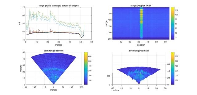
But after I set anglesToSteer=[-60:1:60], the collected data has problems with the ranges under certain BF angles (there were no changes to the environment) as follows: 

Such problems emerged as I generated data for several times. Was it because the angle I set was too large? But in the technical handbook, anglesToSteer=[-60:0.5:60]. Or are there any other factors that I must consider?


Best regards,

Katherine

  • Hi Katherine,

    1) Can you let us know which example code you are referring to?

    2) "anglesToSteer=[-30:2:30]" Can you let us know what this actually implements on the device. Are you moving on steps of 2 degrees? The device has a single step of 5.625 degrees

    3) What is the percentage of error you are observing in both the cases?

    Thanks,

    Pradipta.

  • 1) The data collected was BF data, and Cascade_Configuration_Basic.lua, Cascade_TxBF_dataCapture (SMRR), Cascade_Capture.lua were run respectively.

    2) anglesToSteer=[-60:1:60], I wanted to achieve angle scanning from -60° to 60° with a step of 1°. For The single step of the device is 5.625°. First of all, "anglesToSteer=[-30:2:30]" is the example code, and on page 18 of Imaging Radar Using Cascaded mmWave Sensor Reference Design.pdf, the sentence 'The TX beam is steering within [–60 60] with step size of 0.5 degree' suggests that the step can reach 0.5°. So, my understanding is the scanning angle of BF is not of the same physical quantity as the 5.625° that you mentioned?

    3) After testing, I found that if anglesToSteer*nchirp_loops<2048 (they were all parameters in USRR/LRR/SMRR), the same situation as above would not appear. For example, under the frame based steering mode, if the chirp value of every angle is set at 64, then the maximum scan angle should be less than 32. So, what is the reason for this? The manual doesn't seem to have mentioned it.

    In addition, I am currently doing a comparison between BF and MIMO modes. Could you share the code for Figure 19 in Imaging Radar Using Cascaded mmWave Sensor Reference Design.pdf?

  • Hi,           

        The step size of the Scan will define the number of scan angles and will then define the resolution possible between 2 objects. The default configuration is frame based steering. This is governed by the maximum frame size which TDA can support form capture perspective. This detail is listed in the cascade user guide. I would recommend to tune the

    params.nchirp_loops = nchirp_loops; % Number of chirps per frame
    params.Num_Frames = Num_Frames; % number of frames to collect data 

    In the profile which you plan to use to get the desired resolution at desired range in desired scan window.

    Regards

  • Hello,

    Thank you for your reply.

    As you mentioned, "This is governed by the maximum frame size which TDA can support form capture perspective. This detail is listed in the cascade user guide". Where could I find it in the cascade user guide? I looked through the cascade user guide but I didn't find it.

    Besides, my configuration is set as you suggested. It's as follows:

    function [params] = chirpProfile_TxBF_USRR()
    
    % TI cascade board antenna configurations
    
    platform = 'TI_4Chip_CASCADE';
    
    %% fixed antenna ID and postion values for TI 4-chip cascade board. Should not be changed if user is based on TI board
    TI_Cascade_TX_position_azi = [11 10 9 32 28 24 20 16 12 8 4 0 ];%12 TX antenna azimuth position on TI 4-chip cascade EVM
    TI_Cascade_TX_position_ele = [6 4 1 0 0 0 0 0 0 0 0 0];%12 TX antenna elevation position on TI 4-chip cascade EVM
    TI_Cascade_Antenna_DesignFreq = 76.8; % antenna distance is designed for this frequency
    speedOfLight = 3e8;
    params.Tx_Ant_Arr_BF = [ 12:-1:4]; %TX channel IDs to use for beamforming; all 16 RX channels are enabled by default
    params.D_TX_BF = TI_Cascade_TX_position_azi(params.Tx_Ant_Arr_BF); %TX azimuth antenna coordinates in unit of half lamda
    
    % params.D_RX = D_RX; %RX channel azimuth location in the unit of half wavelength
    params.RadarDevice=[1 1 1 1]; %set 1 all the time
    params.Rx_Elements_To_Capture = 1:16; %All Rx
    
    
    %% define what angles to steer in TX beamforming mode
    params.anglesToSteer=[-60:1:60]; % angles to steer in TX beamforming mode, in unit of degrees
    % params.anglesToSteer = -20*ones(1,5);
    params.NumAnglesToSweep = length(params.anglesToSteer);
    
    %% chirp/profile parameters
    nchirp_loops = 64;
    Num_Frames = 5;
    params.Start_Freq_GHz = 77; % starting fequency for chirp, make sure the entire BW is within 76~77 or 77~81
    params.Slope_MHzperus = 79; % MHz/us
    params.Idle_Time_us = 5; % us
    params.Tx_Start_Time_us = 0; % us
    params.Adc_Start_Time_us = 6; % us
    params.Ramp_End_Time_us = 40; % us
    params.Sampling_Rate_ksps = 8000; % ksps
    params.Samples_per_Chirp = 256; % Number of samples per chirp
    params.Rx_Gain_dB = 30; % dB
    % Frame config
    params.nchirp_loops = nchirp_loops; % Number of chirps per frame
    params.Num_Frames = Num_Frames; % number of frames to collect data
    params.Dutycycle = 0.5; % (ON duration)/(ON+OFF duration)
    params.Chirp_Duration_us = (params.Ramp_End_Time_us+params.Idle_Time_us); % us
    params.NumberOfSamplesPerChannel = params.Samples_per_Chirp * nchirp_loops * params.NumAnglesToSweep *params.Num_Frames; %number of ADC samples received per channel. this value is used in HSDC for data capture
    
    
    %d = 0.5*actual wavelength/wavelength for antenna design = 0.5 * actual center frequency/board antenna design frequency
    centerFrequency = params.Start_Freq_GHz+(params.Samples_per_Chirp/params.Sampling_Rate_ksps*params.Slope_MHzperus)/2;
    d = 0.5*centerFrequency/TI_Cascade_Antenna_DesignFreq;
    params.d_BF = d;
    
    
    %advanced frame config
    params.Chirp_Frame_BF = 0; % 1 - chirp based beam steering, 0 - frame based beam steering
    params.numSubFrames = 1;
    %paramters for subframe 1
    if params.Chirp_Frame_BF == 0 % frame based
    params.SF1ChirpStartIdx = 0; %SF1 Start index of the first chirp in this sub frame
    params.SF1NumChirps = 1; % SF1 Number Of unique Chirps per burst
    params.SF1NumLoops = nchirp_loops;% SF1 Number Of times to loop through the unique chirps in each burst
    %multiply 200 to convert the value to be programed to the register %example:2000000=10ms
    params.SF1BurstPeriodicity = (params.Ramp_End_Time_us +params.Idle_Time_us)...
    *nchirp_loops /params.Dutycycle*200; %example:2000000=10ms
    params.SF1ChirpStartIdxOffset = 1; % SF1 Chirps Start Idex Offset
    params.SF1NumBurst = params.NumAnglesToSweep; % SF1 Number Of Bursts constituting this sub frame
    params.SF1NumBurstLoops = 1; % SF1 Number Of Burst Loops
    params.SF1SubFramePeriodicity = params.SF1BurstPeriodicity*params.NumAnglesToSweep;%SF1 SubFrame Periodicity
    elseif params.Chirp_Frame_BF == 1 % chirp based
    params.SF1ChirpStartIdx = 0;
    params.SF1NumChirps = params.NumAnglesToSweep;
    params.SF1NumLoops = nchirp_loops;
    %multiply 200 to convert the value to be programed to the register %example:2000000=10ms
    params.SF1BurstPeriodicity = (params.Ramp_End_Time_us +params.Idle_Time_us)...
    *nchirp_loops /params.Dutycycle*200 * params.NumAnglesToSweep ;
    params.SF1ChirpStartIdxOffset = 1;
    params.SF1NumBurst = 1;
    params.SF1NumBurstLoops = 1;
    params.SF1SubFramePeriodicity = params.SF1BurstPeriodicity;
    
    end
    
    %frame repitition time in unit of ms. THis based on params.SF1SubFramePeriodicity
    params.Frame_Repetition_Period_ms = params.SF1SubFramePeriodicity/200/1000;
    
    
    %% algorithm parameters
    params.ApplyRangeDopplerWind = 1;
    params.rangeFFTSize = 2^ceil(log2(params.Samples_per_Chirp));
    
    %% derived parameters
    chirpRampTime = params.Samples_per_Chirp/(params.Sampling_Rate_ksps/1e3);
    chirpBandwidth = params.Slope_MHzperus(1) * chirpRampTime; % Hz
    rangeResolution = speedOfLight/2/(chirpBandwidth*1e6);
    params.rangeBinSize = rangeResolution*params.Samples_per_Chirp/params.rangeFFTSize;
    
    end

    Regards,

    Katherine

  • HI,

                 You can find the guide at

    C:\ti\mmwave_studio_03_00_00_14\docs\mmwave_studio_cascade_user_guide

    Also, in the script can you try with 

    nchirp_loops = 16;
    Num_Frames = 16;

    Regards