This thread has been locked.

If you have a related question, please click the "Ask a related question" button in the top right corner. The newly created question will be automatically linked to this question.

AWR2243: 40MHz overlapped in tx signal in continous mode

Part Number: AWR2243

Hello,

we design our own board with 4 AWR2243 (ES1.0) chips in cascade.

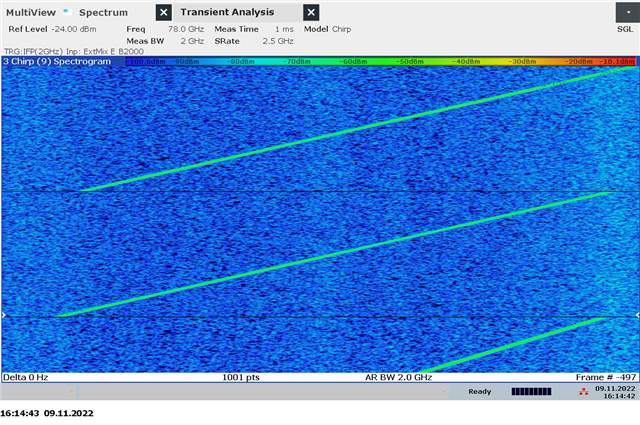
To analyse the quality of the tx signal, we set contious mode with the function 

rlSetContModeConfig
and
rlEnableContMode
.

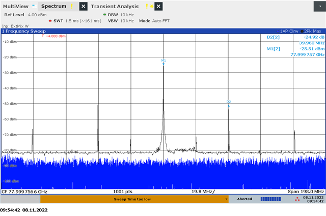
In the spectrum we can see a 40MHz signal overlapped with tx output signal. We assume that the 40MHz signal comes from the quartz crystal "XTAL".

We see this effect on all tx-antennas and in the complete frequency range (76-81GHz).

Have anyone see this effect also on the ESM evalution board?

Hope anyone can give a feedback

  • Hi,

    Is this observed only during the Continuous mode or with framing mode as well?

    Let me discuss your result with team internally and come back by 2 days.

    .

    Another point I observe that you are using AWR2243 ES1.0 not the ES1.1 (production sample)

    .

    Regards,

    Jitendra

  • Hello,

    we can not measure this effect in FMCW mode. But we are not sure if this effect also occour in FMCW mode.

    We have problems with strong targets. With strong targets the noise in the range direction will be increased. We can explain this by bad phase noise, unlinear fmcw ramp or a parallel ramp as we can see in cw mode.

    Here you can see two range slice from Range-Doppler-Map. The red graph is a doppler bin without any target and represent our noise. The blue graph is a walking person in distance of about 1,2m. We can not explain the blue graph from range bin 50 to 250.

    2. Why have a walking person in 1,2m distance impact of 200 rangeBins (6m).

    3. We use the AWR2243 ES1.0

    Thanks

  • Hi,

         Did you try the continuous mode operation with Studio also? We need to ensure that the settings are all correct. 

    regards

  • Hi,

    what do you with mean with

    Did you try the continuous mode operation with Studio also?

    We design our own board and can not use Studio.

    We set the continous mode with help of "mmwave_dfp_02_02_00_03\ti\example\mmWaveLink_Cascade_Example" of the device firmware package.

    We implement the continous mode with help of chapter 6.4 Comtinuous streaming (CW) mode (in cascaded device case) of the "mmWave-Radar-Interface-Control" from device firmware package "mmwave_dfp_02_02_00_03\docs". So all settings should be fine.

    What settings can be wrong to get this tx signal in continous mode?

    Regards