This thread has been locked.

If you have a related question, please click the "Ask a related question" button in the top right corner. The newly created question will be automatically linked to this question.

TDC1000: Ultrasonic wave hopping

Part Number: TDC1000
Other Parts Discussed in Thread: MSP430FR6043

hi:

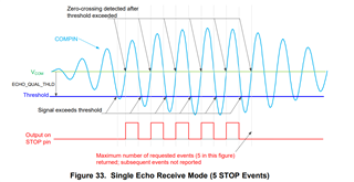
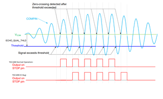
         At present, the TDC1000 has wave hopping. That is, after A detector head is sent to B, B detector head is sent to A. During this period, because the threshold value is the same, but the deviation of the echoes received by A and B will cause A and B to switch to different echo pulses, resulting in a difference of N us, commonly known as wave hopping. Is there any way to solve this problem

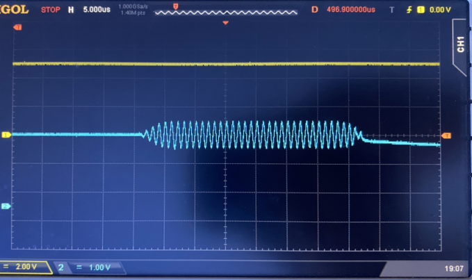
The following blue is the captured COMPIN waveform. It can be seen that the amplitude of the middle waveform is almost equal, so the threshold value can easily switch to pulses at different positions, leading to wave hopping.

  • Hello Kevin,

    Thanks for posting to the sensing forum! This is the first time I hear about wave hopping, so I am not sure if I completely understand this concept.

    Please let me know if I understood this correctly:

    Unit A sends a pulse train to unit B and at the same time unit B sends a pulse train to unit A. Both devices receive a pulse train, but the main problem is that even though both device receive the pulses and even though thresholds are set exactly the same, there is a deviation of a couple of us between each measurement. Wave hopping is essentially the signal not being triggered at the same time in each of the measurements, meaning that it skipped some of the echoes before triggering or "hopped" over some of the echoes.

    Some thoughts on my end:

    There are some things that could affect this, I believe that this could be because of tolerances in the transducers. Meaning that the amplitude and slope of the pulses received by transducer A could be slightly different than the amplitude and slope of pulses received by the transducer in unit B. Contributing to the delay between both measurements.

    Notes on the COMPIN signal provided:

    Even though the signal at the COMPIN signal portion is almost equal this should not really matter, I am not sure what receive mode the customer is using on their system but the STOP signal is supposed to generate after the first zero cross once the threshold is met, as demonstrated in the image below. This is true for single echo and multiple echo mode. The only difference is that single echo will generate a pulse after every single zero cross and multiple echo will generate one long pulse until the threshold is not met.

    If I understood the issue correctly, I think the main problem though might stem from a bug on the TDC1000 device. The bug is that the device can sometimes miss the first zero crossing pulse generation, that means that even though the signal met the threshold, at the first zero cross the STOP signal might not generate. As a workaround to this bug we normally recommend to take the average of a couple of measurements, this will help reduce the us of error caused by the missed pulse.

    But please let me know if I understood this issue correctly, if I didnt please feel free to explain again. Thank you!

    Best,

    Isaac

  • Hi,

        We use TDC1000 in this case:

    We want to send pulses from unit A and receive pulses from unit B at T1; The pulse is sent from unit B and received by unit A. The time is T2. The flow rate is calculated by subtracting time T2 from time T1. We now find that when the water completely submerges the A and B transducers, wave hopping will not occur. When the water does not completely submerge the A and B transducers, wave hopping is very easy to occur.

    So I want to know whether wave hopping is easy to occur when the transducer is not completely flooded, and whether there is any solution.

  • Hello Chao,

    Thanks thanks for the clarification on the use case for the TDC1000. I still don't understand what the wave hopping phenomena is, if you could explain what wave hopping is I might be able to figure out what is going on and provide some suggestions.

    On another note the TDC1000 is not the recommended sensor for flow rate measurements, due to the missed first zero crossing behavior I mentioned in my last post. This unfortunately reduces the accuracy of your flow measurement. If you are looking for a high accuracy solution the our recommendation for high accuracy flow measurements the recommend is to use the MSP430FR6043.

    Best,

    Isaac

  • Wave hopping is actually a problem of zero crossing detection error. For example, if a trigger threshold is set, the STOP of A ->B will be generated in the fourth pulse, but B ->A will be generated in the fifth pulse, which is equivalent to that B ->A skips the fourth pulse, detects the fifth pulse, and skips a pulse.

    At present, we find that wave hopping is now the case when the transducer is not completely submerged. If it is completely submerged, there will be no such phenomenon.

  • Hello Chao,

    Thanks for the explanation on this, if the transducer is not properly submerged then the waves cannot propagate properly through the medium. First thing that comes to mind is that high frequency (500kHz and higher) ultrasonic signals tend to attenuate faster since they do not carry much energy as lower frequency ultrasonic pulses. If the waves have to traverse through different mediums this can also cause some delay since the speed of sound can vary through mediums or can cause additional attenuation to the transmitted pulse.

    Like I mentioned TDC1000 does have a problem with the zero crossing, it may sometimes generate the STOP pulse a whole pulse late this is this device is not the most accurate for flow measurements. There is not a setting that can really improve the wave hopping in that instance if you encounter this issue, the only thing that can help would be to use averaging in order to increase the accuracy of the measurements.

    Best,

    Isaac

  • Hi,

         Can you explain the following in detail? I don't understand。

         “TDC1000 does have a problem with the zero crossing, it may sometimes generate the STOP pulse a whole pulse late”

  • Hello Chao,

    I think it may be easier to use an image to describe the issue, so I have included an image below. In the top red waveform shows the behavior of a TDC1000 that is operating as it intended, but the bottom shows the issue with the zero-cross comparator bug that I mentioned. Even though the signal at the zero cross comparator is enough to trigger a STOP pulse, when the bug is present the device will miss the first STOP pulse generation. Meaning that it will generate the first STOP where the second STOP pulse should be. This can cause some delay in your measurements which is why this is not the most accurate solution. The missed zero cross does not happen every measurement which is why averaging can help reduce the impact of the missed pulse.

    Best,

    Isaac

  • Hello Isaac,

         Thank you. I understand the zero crossing error of the TDC1000. This looks like the same phenomenon as what I said about wave hopping. At present, as long as the transducer is completely submerged, it seems that there is no such zero crossing detection error during our test. Only when the transducer is submerged half or 90%, wave hopping is easy to occur. Especially when the transducer is flooded by 90%, the probability of abnormal value and normal value caused by this wave hopping phenomenon is 50%, which should not be zero crossing detection. Therefore, whether there is a necessary condition for the TDC1000 usage scenario is that the transducer needs to be completely immersed.

  • Thanks for the information Chao,

    It seems like the transducer needs to be completely submerged in this instance. You should check a couple of other transducers just to make sure that they all follow this similar behavioral trend in your system.

    Best,

    Isaac