This thread has been locked.

If you have a related question, please click the "Ask a related question" button in the top right corner. The newly created question will be automatically linked to this question.

FDC2212: FDC2212 cannot read data

Part Number: FDC2212

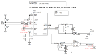
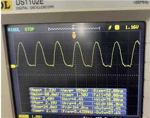
Problem description: Currently, the Manufacturer ID and Device ID can be read normally. The CH0 channel can observe the signal through the oscilloscope, but the data read by the software is always 0; The same software is normal on the circuit board of other projects, and the current circuit board has been changed to be consistent with it. The circuit diagram of FDC2212 is as follows:

  • You mentioned your software works with other projects.
    Do your other projects use the FDC2212, or do they use a different device?

    What I2C address are you using for the FDC2212?

    Are you putting the FDC2212 into Sleep mode when you configure it?

    Regards,
    John

  • FDC2212 is also used in other projects;

    FDC2212 pin 4ADDR in the circuit diagram is grounded. According to the manual, IIC address is 0x2A;

    When configuring the register, first set it to sleep state, then configure the registers whose addresses are 0x08, 0x10, 0x14, 0x19, 0x1B and 0x1E respectively, and finally configure the address 0x1A to enter the working state.

  • A few more questions:
    1. Is this a custom PCB or one of our EVMs?
    2. What is the sensor frequency design goal, and what is the actual measured frequency?
    3. Is this for one PCB, or multiple PCBs?

    Regards,
    John

  • This is a customized PCB, drawn by our company's hardware engineer;

    As for the sensor frequency, I understand that the host IIC sets the frequency as 50kHz; 50kHz measured by oscilloscope;

    There are 3 customized PCB boards in this project, and the problems described previously have occurred.

  • Thank you for he additional information.

    Let's start by confirming the sensor behavior is as expected, and we will work our way towards the output.

    Your schematic shows and on-board L = 18uH and a resonant C = 33pF.
    Ignoring any capacitance from the sensor, that gives a resonant frequency of about 6.5MHz, which is much higher than the 50kHz mentioned earlier. 
    If you assume the sensor adds the largest specified capacitance (=250nF), then the sensor frequency should be around 75kHz, which is still exceeds 50kHz.

    So the expected sensor behavior is differs from what has been observed.

    I believe the best way to move forward is to carefully measure the sensor waveform with the device in conversion mode.
    The best way to do this is to use a high-impedance probe with a 1k resistor between the probe tip and the test point on the PCB. 

    Please give that a try and attach the captured waveforms to this thread. 
    Once we can confirm the sensor waveforms (INxA, INxB) look okay for offset, amplitude and frequency, we can go from there.

    Just so you know, Thursday and Friday holidays here in the US, so responses will be slow.

    Regards,
    John

  • The 50kHz I mentioned means that the output frequency of the host is 50kHz, which is not the same concept as the sensor frequency you mentioned; Because this circuit board has been debugged with problems, it was later modified to the same circuit as other projects. The L301 inductance in the figure below was replaced with 10uH, and the frequency of Pin1 waveform measured by the oscilloscope in J104 was about 5.4MHz. The waveform picture of the oscilloscope in the figure below can be seen.

  • Hi,

    Our team is currently out for the Thanksgiving holidays.  We should be able to look into your question again when we are back on Monday.

    Thank you,

    Mekre

  • Your sensor signal looks okay.
    And if I understand correctly, the I2C interface allows you to read/write other parameters (?).
    If you have seen this happen on multiple PCBs, then I'm stumped as to the root cause.
    Regards,
    John

  • I spoke with a colleague and he suggested checking the CONFIGURATION register (0x18)  for reported errors.
    Do you see any error flags in this register?

    Regards,
    John

  • Read the 0x18 register, and the returned data is 0x0000.

  • Thank you for the information.
    I will consult with one of my team members and update this thread by Tuesday.

    Regards,
    John

  • To go forward we will need more info, like a full schematic, layout, and BOM.
    I will close this thread and send you a friend request. Please accept it and we can privately message thru this forum.

    Regards,
    John