


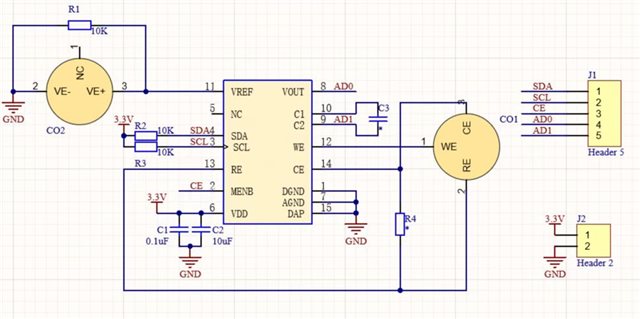
MCU:MSP430。PML91000 is used to collect CO, CO2, currently we are experiencing some configuration problems, please help take a look. We just added a gas collection function to the original meter module, and the program also added this part of the function on the basis of the original, and the configuration data and the block diagram are as follows:
configuration data:
#define LMP_WRITE_ADDE 0x90 //LMP写+地址
#define LMP_READ_ADDE 0x91 //LMP读+地址
#define LMP_REG1_ADDE 0x00 //LMP STATUS 0x00
#define LMP_REG2_ADDE 0x01 //LMP LOCK 0x01
#define LMP_REG3_ADDE 0x10 //LMP TIACN 0x10 TIA Control Register (Address 0x10)
#define LMP_REG4_ADDE 0x11 //LMP REFCN 0x11 Reference Control Register (Address 0x11)
#define LMP_REG5_ADDE 0x12 //LMP MODECN 0x12 Mode Control Register (Address 0x12)
木卮子 15:11:54
/*氧气*/
#define LMP_REG2_UNLOCK 0x00 //LMP 0 Registers 0x10, 0x11 in write mode 0x00
#define LMP_REG2_LOCK 0x01 //LMP 1 Registers 0x10, 0x11 in read only mode (default) 0x01
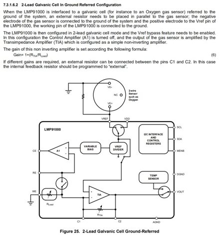
#define LMP_REG3_DATA 0x08 //LMP 0x0E 见P22 3.5kΩ //0x0F
#define LMP_REG4_DATA 0xc0 //LMP 0xB0 见P22 参考电压为外部源,内部零选择(源引用的百分比)67% //0xB0
#define LMP_REG5_DATA 0x01 //2-lead ground referred galvanic cell
Fetch data as configured above,as follows:
uint LMP_Read_Func(void)
{
unsigned char un8Date;
un8Date = 0;
PLMStartI2C();
PLMWrByte(LMP_WRITE_ADDE); //发送LMP91000地址
i2c_WaitAck();
PLMWrByte(LMP_REG3_ADDE); //发送寄存器地址
i2c_WaitAck();
PLMStopI2C();
PLMStartI2C();
PLMWrByte(LMP_READ_ADDE); //发送LMP91000地址
i2c_WaitAck();
un8Date = PLMRdByte(noACK);
PLMStopI2C(); //产生一个停止条件
return (un8Date);
}
The return value is always 1
when PLMWrByte(LMP_REG3_ADDE); This step is changed to: PLMWrByte(LMP_REG1_ADDE);The return value is 129, which should be the read state.
My question is:
1, is the configuration correct
2. Whether the process of fetching numbers is correct
3, how to parse the return value (no instructions on the document)
