Hi team,
Here's an issue from the customer may need your help:
1) The customer made some changes to the original DPC based on demo:
Changed data layout and number of bits after 2DFFT to make 3DFFT results exported from 2DFFT using matlab inconsistent with results directly using hardware accelerator for 3DFFT.
The original data was laid out continuously in accordance with TX1 TX3 TX4 TX2, modified to TX1 TX2 TX3 TX4 and discontinuous. A total of 43 bits of data after zeroing between 16 virtual channels are 3DFFT, all 16 virtual channels are horizontal antenna virtual channels.
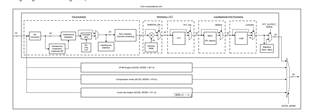
The hardware accelerator that performs 3DFFT has also been changed by the customer. The size of the dopplersubmat is 43*dopplerbins(number of dopplerBin per subband)*bytespersample(8byte)*2(ping pong). Change srcAidX in HWA configuration to 42 and angle FFT to 64. Obj->cfarAzimFFTCfg.numAzimFFTBins = 4 * mathUtils_getValidFFTSize(16); SrcBidx = 43*bytespersample; corresponding change to EDMA, change account to 43*bytespersample. SrcBidx = 43*bytespersample, dstBidx = 43*bytespersample; and so on.
The above changes are in the functions DPU_DopplerProcHWA_configHwaCFARAzimFFT and DPU_DopplerProcHWA_configEdmaAzimFFTIn.
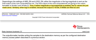
The customer has modified the memory size of the associated data used by the hardware accelerator, the data read from the hardware accelerator, the size of the FFT, and the associated EDMA.
Are the above changes possible? What other changes are needed? Is there a configuration tutorial available for using the hardware accelerator?
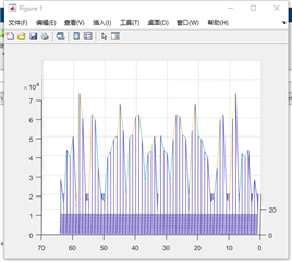
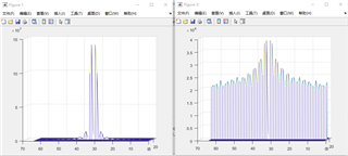
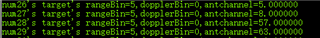
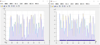
2) They also tried the data injection test, only the first Doppler unit of the 10th distance gate was injected, the other full assignment was 0, and the injected test data was a sinusoidal signal as follows:
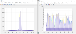
The figure on the left shows the data exported by dopplersubmat (processed with matlab), and the figure on the right shows the data exported by AzimuthScratchBuf after 3DFFT, which is also 0 on the other range units. There are no peaks, which are consistent with the results of the matlab simulation.
3) The customer sets cmultScaleEn to disable because each iteration reads 43 bits of data into the Hwa memory. According to the TRM, if this bit is set to disable and cmultMode = 0110b, the sample read is multiplied by the number in Vector multiplication Cofficient RAM. Changing the vecMultiMOde1RamAddrOffset=172 (offset 43 bits) does yield a different result than before.
How to change the data in Vector multiplication Cofficient RAM? What value is required to change if you want to keep the sample read unchanged?
Use the function HWA_configRam(obj->hwahandle,HWA_RAM_type_VECTORMULTIPLY_RAM, &Buffer[0],86*sizeof(Int32_t),0)) make a modified assignment to this section of memory, but the board will get stuck in the DPC. According to the TRM, the RAM supports up to 1024 data, and the startIdx = 0 set by the customer should be no problem.
Could you help check this case? Thanks.
Best Regards,
Cherry