


Hi team,
Based on the AWR1843 chip, we designed our own radar hardware board. The power supply solution used the official LP87702D. When we were debugging the AWR1843 chip, some hardware boards failed to start or work normally after being powered on.
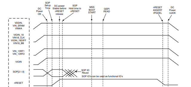
We debugged the problematic hardware board and powered the chip with the 3.3V, 1.8V, and 1.0V voltages. Everything was normal. I used an oscilloscope to measure the power supply and reset signal timing, which also met the requirements in the manual. (The rising edge of the nReset reset signal was about 10ms later than the VIOIN power supply)
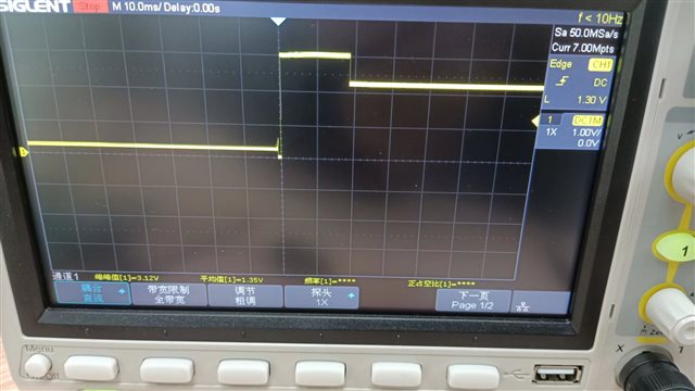
However, when measuring the WARMRESET OUTPUT signal, I found the waveform was as follows. The signal was abnormal, and the level voltage was consistently maintained at 2.2V.
I measured the VBGAP OUTPUT output signals. They were all of low-level electricity (0V), under normal circumstances there should be an output of 1V.
I measured the 40M crystal oscillator and found there was no oscillation waveform output. I've checked that there is no problem with the matching capacitor.
In addition, after the above abnormalities were found on the radar board, I powered off and powered on within 2s, and the chip could start normally. I tested the WARMRESET OUTPUT signal, VBGAP OUTPUT signal, and 40M crystal oscillator frequency, and they were all normal.
So could you please tell me the specific reason for this problem? Are there specific requirements for the rising edge delay of the reset signal? Or will it be OK if the delay is greater than 3ms?
Kind regards,
Katherine
