Other Parts Discussed in Thread: MMWAVEICBOOST
I am working with the eval board ISK and I get the same effect. So the hardware is fine. And the SPI drive modification didn't help too.
What can I do?
Thank you in advance!
This thread has been locked.
If you have a related question, please click the "Ask a related question" button in the top right corner. The newly created question will be automatically linked to this question.
I am working with the eval board ISK and I get the same effect. So the hardware is fine. And the SPI drive modification didn't help too.
What can I do?
Thank you in advance!
Hello,
Could you please confirm any modifications done on the SDK?
if yes which could you please post changes done on the SDK side?
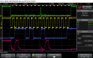
Also please provide SDK version? Also could you please elaborate on same effect that mentioned above? If you have any oscilloscope/ LA captures would be helpful.
thanks and regards,
CHETHAN KUMAR Y.B.
Hello user5115653,
Thank you for sharing the SDK version and Oscilloscope waveform, Could you please explain what you were trying to do and where is the anomaly?
Is the SPI is connected any secondary device? What address you are trying to write/read? How is the hardware connection?
Standalone IWR6843ISK doesn't use SPI interface, Hence could you please explain your setup?
Thanks and regards,
CHETHAN KUMAR Y.B.
Hello Chethan,
Thank you for your message!
I work with the IWR6843ISK on the MMWAVEICBOOST board. The ISK works as spi master and trying to read 3 register sequential from address 0 to 2. Each register has 1 Byte information. With this sequential access I receive more data faster.
So the communication (byte to byte) should run like:
MOSI: Address - D1 - D2 - D3 (0x00 0x00 0x00 0x00)
MISO: Status - D1 - D2 - D3 (0xSS 0xd0 0xd1 0xd2)
The situation is the slave device understands the peak in CS as a new communication start. It thinks:
MOSI: Address - D1 - Address- D1 (0x00 0x00 0x00 0x00)
And it answers:
MISO: Status - D1 - Status – D1 (0x80 0x82 0x80 0x82)
The SPI settings are:
    params.mode = SPI_MASTER;
    params.frameFormat = SPI_POL1_PHA0;
    params.pinMode = SPI_PINMODE_4PIN_CS;
    params.dmaEnable = 0;
    params.csHold = 0;
    params.dataSize = 16U;

    params.u.masterParams.bitRate = 4000000U;
    params.u.masterParams.numSlaves = 1;
    params.u.masterParams.c2tDelay = 0x00;
    params.u.masterParams.t2cDelay = 0x00;
    params.u.masterParams.wDelay = 0x00;

    params.dmaHandle = gDmaHandle;
    params.u.masterParams.slaveProf[0].chipSelect = 0;
    params.u.masterParams.slaveProf[0].ramBufLen = MIBSPI_RAM_MAX_ELEM;
    params.u.masterParams.slaveProf[0].dmaCfg.txDmaChanNum =1U;
    params.u.masterParams.slaveProf[0].dmaCfg.rxDmaChanNum =0U;
Thank you again!
Hello user5115653,
Thanks for providing the setup condition, Could you please provide which slave device you are trying to read & which interface in MMWAVEICBOOST using for the SPI ? And at what frequency you are trying to read? Is the slave compatible for the MibSPI protocol?
The devices SPI IP uses a MibSPI Protocol by TI.

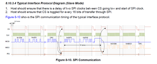
For the SPI operation CS signal must be toggled for every 16 clocks or programmed data size, could you please check the compatibility with the peripheral connecting to the SPI port?
Thanks and regards,
CHETHAN KUMAR Y.B.
Hi Chethan,
the slave device is not a TI one. I will check if it is compatible with MibSPI Protocol. But if the CS must be toggled for every 16 clocks, I suppose it is not.
You told about "or programmed data size". Could it be possible to set the data size to 16 x 16 clocks? That would be a good solution. Wouldn't it?
The frequency I've tried is 4MHZ. The quality of the signal above this frequency is not very high (I think with a pcb from us will be better, because I work with three eval boards)
Attached the interface in MMWAVEICBOOST using for the SPI:
Thanks!
Hello user5115653,
Thanks for the confirmation, Understood that slave device is not TI, Hence Its good to check the SPI protocol compatibility with the TI device.
Yes, three boards stackup adds larger parasitic on the SPI lines, Hence it may not be operational at higher frequency. You could try even lower frequency if there are long cables from the MMWAVEICBOOST board to SPI peripheral.
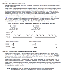
For keeping CS line active low, you may want to use CSHOLD Bit as described in the Technical reference manual shown below, it may help to overcome this problem.


Thanks and regards,
CHETHAN KUMAR Y.B.
Hello user5115653,
Using CSHOLD with CHARLEN = 0x8 should get the desired result.
Thanks and regards,
CHETHAN KUMAR Y.B.
Hello Chethan,
do you mean with CHARLEN =0x8 params->dataSize, doesn't you?
I need to read/write sometimes 1 byte (here I have no problems with params->datasize = 16U) and sometimes data bytes up to 16 bytes. But I can only change the cshold bit when I intialize the SPI port. Or you mean is it possible to change the cshold for each word?
Thanks a lot!
Hello again,
With dataSize = 8U I got the peak after 1 byte und that reset the spi communication

Hello user5115653,
Thanks for posting the observation, could you please set the data size to 16 x 16 clocks for larger data transaction ?
Thanks and regards,
CHETHAN KUMAR Y.B.
Hello Chethan,
I can only set params.dataSize = 8U or 16U.
Sorry but I don't understand 16 x 16...
Thanks and regards!
Hello user5115653,
Is your CSHOLD bit is set?
Thanks and regards,
CHETHAN KUMAR Y.B.
Hello Chethan,
CSHOLD is 0.
I need sometimes to read or write only two bytes. And for data acquisition 16 bytes. Because of that I need the CS return high after the read or write.
Thanks and regards
Hello user5115653,
I may need to refer this to software expert.
Thanks and regards,
CHETHAN KUMAR .B.
Hi,
My apologies for the delay here. This may be possible by dynamically changing the CSHOLD value depending on which of those two scenarios you are in, however this is certainly not something which is tested in our SDK. I would recommend you first try altering the SPI CSHOLD value dynamically (you will likely need to add code to directly write to the corresponding SPI module driver).
Best Regards,
Alec