This thread has been locked.

If you have a related question, please click the "Ask a related question" button in the top right corner. The newly created question will be automatically linked to this question.

LDC2114: LDC2114

Part Number: LDC2114
Other Parts Discussed in Thread: , LDCCOILEVM, LDC2112, LDC3114, FDC1004

Dear all,

I am in process of designing an inductive buttons.  In my design I am interested to use the LDC2114 and the size of the coil would be around 4 mm.  There will be some plastics (I am not sure of the material and the dimension yet)  between the coil and the shaft of the button pressed.  Is there a relationship that I would know the following please:

1- What would be the size of the shaft if my coil is 4 mm? 

2- What material should be my shaft to have a better detection?

3- How thick and what material would be the plastic?

4- How far should be the distance between the shaft and the plastic?

Thanks in Advance,

Ali

  • Sorry, one additional question please.  I can not find GUI for the LDC2114 EVM.  I understand the GUI should work for all the LDC's evm but mine is not working.  I did download snoc028f file but I can not getting to work.  Please help.

  • Hello Ali, 

    Based on your information, I assume the shaft is also your metal target for this button implementation. With that in mind, here are some answers to your questions: 

    1. The target size needs to be larger than the coil size for best performance. This E2E post covers the impact of target size compared to coil size: https://e2e.ti.com/blogs_/b/analogwire/posts/inductive-sensing-target-size-matters 
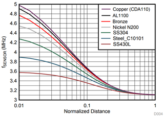
    2. Inductive touch buttons can work with any conductive material but metals like copper, aluminum, and stainless steel work best. Here is a graph showing how much frequency shift you get for different metals with the same sensor coil (more change is better): 
    3. The plastic that is between the coil and target needs to allow the target distance to be between 3% and 20% of the coil diameter for best results. For a 4mm coil, this would be between 0.12mm and 0.8mm thick. Having the plastic any thicker (and therefore having the metal farther away) decreases the inductance shift that occurs for a given shift in the metal. If you have a large enough change in target distance, you can still make a farther target distance work. 
    4. Distance between the plastic and metal does not matter as long as you have enough motion in the shaft for the sensor to accurately detect a button press. For the recommended range (0.12mm to 0.8mm) LDC devices can detect button presses with target motion in the μm range. Again, if you are farther away, you will need more motion in your target to accurately detection a button press. 
    5. SNOC028f is the latest version of the GUI for the LDC2114EVM. What issues are you having getting it to work? Here are a couple basic debug steps that might help:
      1. Did you install the GUI with admin rights? 
      2. Is the EVM showing up in the device manager of your computer? 
      3. If the EVM is connecting but communication to the GUI is not working smoothly, have you done a firmware update? 

    Best Regards, 

    Justin Beigel

  • Dear Justin,

    Thank you for your reply.  I will look into it and get back with you. I also have the following questions please.  I need to design a 4 mm coil as I mentioned it before.  I am aware that there is a design tool for designing the coil.  My question is while design the coil would it be more sensitive if the number of turn increased or the width of the trace?  How about the spacing between the trace please?  Is there an application note that goes into detail about the coil designing?  How do I calculate the caps in parallel with the coil.  

    I got the SNOC028f  working.  Thank you.

    Warm Regards,

    ALi.

  • Hello Ali, 

    The number of turns and trace width will impact the Rp of the coil and therefor impact the Q of the coil design. Increasing the number of turns can be helpful to a point but the inner most turns do not make much difference for close target distances as with button applications so we recommend setting the number of turns to ensure the inner diameter of the coil is between 20% and 80% of the outer diameter to keep the Q factor high. With the LDC2114, you need to keep your Q factor between 5 and 30 but it is best to keep it at the higher end of the range. The capacitor choice will mainly impact the Q factor and the sensor frequency. Once you have a general coil design in place, you can adjust the capacitor to help keep the resulting coil properties within the devices specifications. 

    Best Regards, 

    Justin Beigel

  • Dear Justin,

    Your replies are very helpful.  I truly appreciate it.  I have following questions.

    Please be reminded that I will design my coil on a flex PCB rather than rigid PCB.  Would this make any difference?

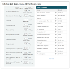
    I have designed my coil based on following parameter.  I would appreciate to hear your comments,

    My other question is related to the LDCCOILEVM Evaluation Module,

    LDCCOILEVM Evaluation board | TI.com

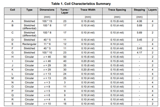
    There are several coils on this module included 4 mm.  Can we use the same design for the flexible PCB?  If so, how can I find the parameters related to the 4 mm coil on this module?

    Warm Regards,

    Ali.

  • Hello Ali, 

    That coil design looks fine as is. 

    The parameters for the coils in the LDCCOILEVM can be found in the LDC Reference Coils User’s Guide in table 1: 

    Implementing it on a flex PCB is okay but it will change the layer thickness which impacts the self mutual inductance between layers of the coil. This isn't an issue it is just something to keep in mind as your resulting inductance of the coil will vary from that of the LDCCOILEVM slightly. 

    Best Regards, 

    Justin Beigel

  • Dear Justin,

    Thank you.  Is there a tool that I can adjust the design for the case of flex PCB please?

    Warm Regards,

    ALi.

  • Hello Ali, 

    You can change the layer thickness in the webench coil designer tool you shared a screenshot of or you can use the excel spreadsheet found at https://www.ti.com/tool/LDC-DESIGN-TOOLS to adjust the layer thickness and see the change in coil properties. 

    Best Regards, 

    Justin Beigel

  • Dear Justin,

    Changing the layers is not the issue but how much to change to get the right coil on the fles is my concern please?

    Thanks,

    Ali.

  • Hello Ali, 

    The layer height you need to put in for your flex PCB depends on the manufacturing properties of the board. You will need to double check with your PCB manufacturer on what supported layer thicknesses are for the flex PCB. 

    Best Regards, 

    Justin Beigel

  • Dear Justin,

    With my current design for detecting the button pressed with a shaft of 2mm max and a 4mm coil on a flex would you recommend another LDC rather than LDC 2114 please?

    Warm Regards,

    Ali.

  • Hello Ali, 

    For button applications, the LDC2112, LDC2114, and LDC3114 are our top recommended devices because they have a built in button algorithm. The LDC2112 is just a 2 channel version of the LDC2114. The LDC3114 has a few differences from the LDC2114 (like access to the raw data before the button algorithm and a few extra settings) but I don't think you need that for this application based on our conversation so far. 

    When you say 2mm shaft max, is this the diameter of the shaft or the length? If it is the diameter that would be above the sensor coil, it would be a good idea to attach a larger (4-5mm) target at the base if possible to increase the impact that the target will have on the sensor coil for a button press. 

    Best Regards, 

    Justin Beigel

  • Dear Justine,

    Like usual appreciate for prompt respond please.  Yes, the diameter of my shaft would be around 2 mm.  I am not sure if I can have the coil size larger than 4 mm.  I was reviewing one of the videos made by TI I see that they have implemented the inductive buttons in a wristwatch.  Is this watch made by TI can we have more info about it please?

    Thanks,

    Ali.

  • Hello Ali, 

    This watch demo follows the design principles discussed in the Inductive Touch Buttons for Wearables (Rev. A) application brief and the LDC2112/LDC2114 Inductive Touch System Design Guide

    The watch buttons showcased in that video follow a similar design to the design guide in terms of coil design and mechanical implementation. 

    Best Regards, 

    Justin Beigel

  • Dear Justin,

    Thank you for all your reply.  I am checking to see if there is any other question before I confirm this issue is resolved.

    Warm Regards,

    Ali.

  • Hello Ali, 

    Sounds good. I will mark this thread as closed for now. Feel free to mark an answer as 'resolved' or reopen the thread once you can. 

    Best Regards, 

    Justin 

  • Dear Justin,

    I am planning to test my design by selecting the R coil from the LDC Reference Coils Board.  According to the SV601140-001_Schematic it suggests using the MLZ2012N6R8LT000 TDK Corporation | Inductors, Coils, Chokes | DigiKey as a series fixed inductor and 100 pF cap as C-R.  Is it a good starting please?

    Warm Regards,

    ALi.  

  • Hello Ali, 

    The LDCCOILEVM was designed to work with multiple LDC devices. The LDC2114 has a higher frequency limit than other devices so an inductor isn't required for coil R to be used with it. You can just use a 0 Ohm resistor to populate the board instead of the inductor. For more information on how a series inductor impacts the sensor design, see the following post: https://e2e.ti.com/blogs_/b/analogwire/posts/inductive-sensing-how-to-use-a-tiny-2mm-pcb-inductor-as-a-sensor

    Best Regards, 

    Justin Beigel

  • Dear Justin,

    Thank you for very well explanation.  This would resolve my issue but I have some question regarding the FDC1004 please.  Should I open another ticket?

    Any how this is my question.  By FDC1004 can we detect when the watch is touched with water?  If not, how about emerged in the water.

    Warm Regards,

    Ali.

  • Hello Ali, 

    Since this will be a different part and application, you will need to open a new thread with your new question. 

    Best Regards, 
    Justin Beigel