This thread has been locked.

If you have a related question, please click the "Ask a related question" button in the top right corner. The newly created question will be automatically linked to this question.

FDC1004: FDC1004

Part Number: FDC1004

Hello members of the forum, continuing with the query made: “FDC1004: Assistance designing with TI products

After advancing with the experiments and achieving a reasonable variation between the measurements with and without an objective, which would allow the detection of the seedlings.

We are trying to eliminate environmental interference with no success, specifically human interaction with the device, we have applied what is stated in application note SNOA926A, but we get almost identical results to the application without shield.

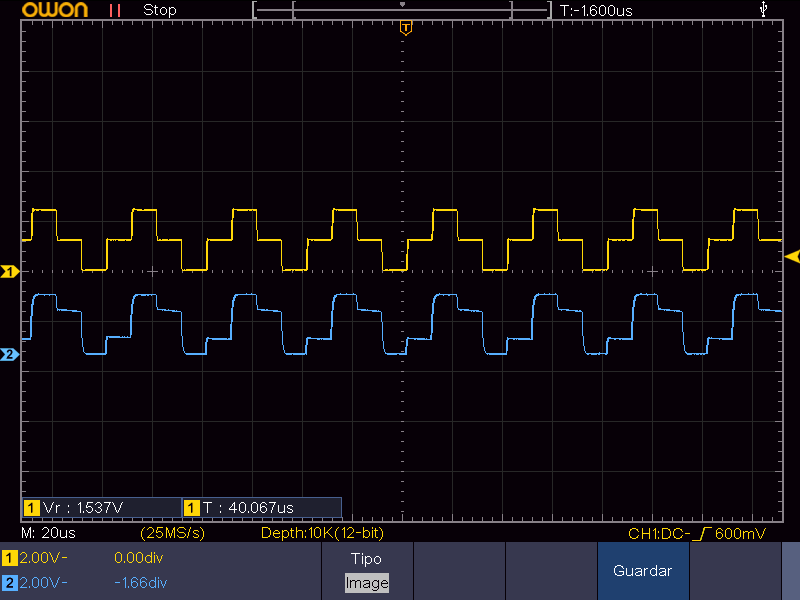
We attach capture of the oscilloscope with CIN4-FDC1004 on channel 1 and SHLD2-FDC1004 on channel 2, we notice that the signals are not perfectly identical, is that the problem for which the shield implementation has no effect?


NOTE: We are working with the following registry configuration:

MEAS1_ = 752 2500

MEAS2_ = 0 0

MEAS3_ = 0 0

MEAS4_ = 0 0

CONF_MEAS1 = 7C00

CONF_MEAS2 = 5C00

CONF_MEAS3 = 1C00

CONF_MEAS4 = 1C00

FDC_CONF = 988

OFFSET_CAL_CIN1 = 0

OFFSET_CAL_CIN2 = 0

OFFSET_CAL_CIN3 = 0

OFFSET_CAL_CIN4 = 0

GAIN_CAL_CIN1 = 4000

GAIN_CAL_CIN2 = 4000

GAIN_CAL_CIN3 = 4000

GAIN_CAL_CIN4 = 4000

Manufacturer_ID = 5449

Device_ID = 1004

Regards, Cesar.

  • Cesar,

    Thanks for your continuing interest in the FDC1004.

    If your system is showing sensitivity to environmental factors, like a human presence, please consider using the out-of-phase technique (OOP) as described in the app note Capacitive Sensing: Out-of-Phase Liquid Level Technique. The app note discusses the details, but in essence an OOP system is a sensor/shield arrangement that causes the measurement medium to be at zero potential.

    The OOP configuration can make the system much less sensitive to the external environment compared to the conventional approach where the medium being measured has a non-zero potential, which can in turn make measurements more sensitive to EMI and nearby conductors, like a human hand. 

    The app note gives guidance on the structure of the sensor & shield as well as the high-level device settings.

    At first sight it can seem kind of weird, so if you have any questions after reviewing the app note, please let me know.

    Regards,
    John

  • Thank you very much for the answer John

    In terms of physics, the OoP application is not entirely clear to us, that is why we consult if the elimination of interference and external noise is in all directions, or only behind the liquid, in view of SHLD1 and SHLD2 (further away from the liquid).

    Figure 5. OoP Technique Sensor Layout for LEVEL and REF Sections

    Regards, Cesar

  • Cesar,

    As I mentioned before, the intent of the OOP technique is to force the liquid to zero potential, where it will be less sensitive to external interference.
    It does this by assigning CHx/SHLD1 and SHLD2 so that SHLD2 is 180deg out of phase with CHx/SHLD1. The only function of SHLD2 is to provide an equal-and-opposite signal w/respect to CHx/SHLD1, thereby forcing the liquid under measurement to zero potential. SHLD2 does no sensing functions. 

    The liquid at zero potential may also help attenuate "front" EMI effects, but how well it does this will be dependent of the properties of the liquid, container, sensors, shields and so on.

    The shields as shown in Fig. 5 will help reduce EMI from the "back" of the system. 

    I hope this helps. Please let me know if you have any questions.

    Regards,

    John