This thread has been locked.

If you have a related question, please click the "Ask a related question" button in the top right corner. The newly created question will be automatically linked to this question.

TMCS1107-Q1: AC Current Measurement

Part Number: TMCS1107-Q1
Other Parts Discussed in Thread: TMCS1107,

Hi ,

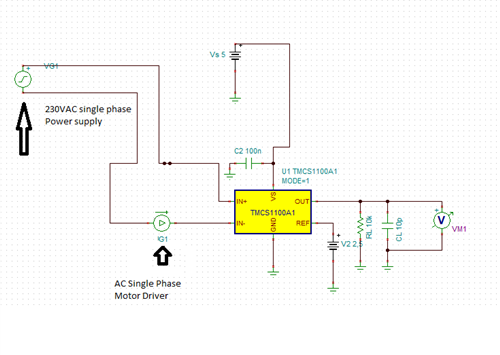
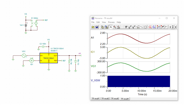
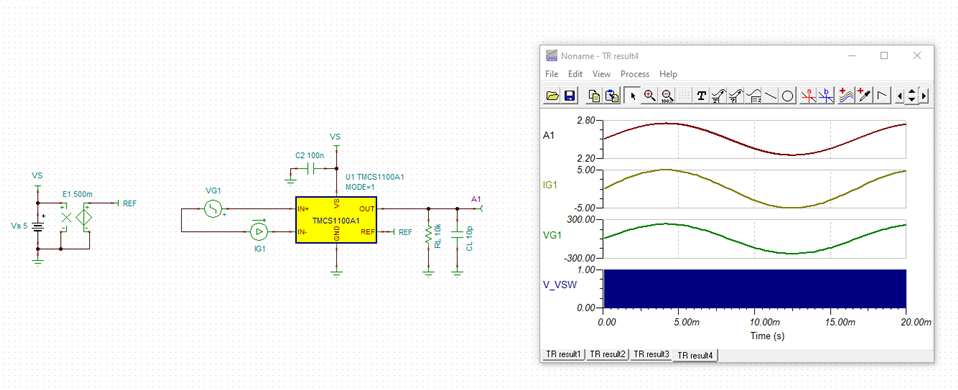
I have a TMCS1107A1BQDRQ1 Hall Effect Sensor from TI, a single phase AC power supply and an AC load. I want to measure the current on the AC line by using the schematics given below, but I couldn't. The sensor's voltage output is always 2.5V regardless of the current drawn by the AC load or the reference voltage. I also tried to measure the current both in high side and low side of the circuit but nothing has changed.

To verify the sensor and the board, I used a DC supply and a DC load and it worked as expected.

What am I missing? Can TMCS1107A1BQDRQ1 be used in both AC and DC applications? If this is the case then what is wrong with my circuit?

Thanks in advance,

  • ilker,

    Happy new year and thanks for using E2E! So I ran a check on this using the same TMCS1100A1 model (there are TMCS1107 models available as well if you'd prefer to simulate with the internal reference), and I believe the issue you're having is due to the way you have wired the loop in the simulation without any reference to GND. If you break the loop between VG1 and IG1 and refer both to GND, you should see this behavior correct itself. 

  • Hi Carolus,

    Thanks for your answer and happy new year to you too.

    In my application, I am trying to measure the current drawn by a single phase 230Vac motor driver. The motor driver is supplied from the main grid, therefore, in the load side there is a 230Vac phase and a neutral connection. The sensor is supplied by an isolated 5Vdc power supply. So, in my application it is not possible to connect the neutral (of the load) to the GND (of the sensor) as it is shown in your schematics.

    In this case, what should be the schematics of the simulation for my application.

    To clarify, my original problem is this. I have a sensor board that uses TMCS1107-Q1. When I connect the board to a 24 VDC system, it is working as expected. But when I connect the same board to measure a single phase 230 Vac system (230Vac and neutral connection and a motor driver), the sensor always give me 2.5V output regardless of the current drawn by the load.

  • Ilker,

    Understood. The point I was making above was more to a termination point for the purposes of the simulation calculating nodes correctly. In some cases when exercising split grounds, you need to place some form of relationship to the true GND of the device for the purposes of getting the simulation to converge (like 1TΩ+). I looked a bit more in depth and it appears for this macro this isn't necessary. I attempted the same loop you have shown and get the following:

    Can I ask where you downloaded the model you're using? I've included the model I compiled above here to help streamline getting you started here. TMCS1100A1 Reference.TSC

  • Hi Carolus,

    Firstly thanks for everything.

    Finally, i created a circuit similar to the last circuit you showed. But still nothing has changed. Actually my problem was using a digital multimeter to measure dc vout. Because the digital multimeter was showing me the Vrms only, so i was only observed 2.5 volts on vout. I had to measure Vpeak to see correct result and i got an correct result when I measured it with an oscilloscope.

  • ilker,

    Ah, this is correct. A DMM is not the ideal measurement device as the RMS output will be dominated by the DC component of the measurement. Glad to see you were able to work this out. Please let me know if there's anything else I can do to assist here!