This thread has been locked.

If you have a related question, please click the "Ask a related question" button in the top right corner. The newly created question will be automatically linked to this question.

AWR2243: After resetting, the receiving gain and transmitting power changed, and the chip performance became unstable

Part Number: AWR2243

Hi Team,

Currently I've adopted the AWR2243 chip cascade scheme. I'm using TDM mode to send waves (8 rounds) to detect vehicle targets on the road. In order to meet the requirements for speed detection, I've used MaxVelocity Extend for speed expansion.

While using it, I found that it wasn't running steadily. Usually, the targets could be detected normally, but the detection effect becomes worse after it ran for dozens of minutes or several hours. Specifically, there were errors in the speed expansion, and there were errors in the speeds and angled detected. It returned to normal after I restarted the RF front-end module using the reset and restart module in mmWaveLink.

This phenomenon lasted for two weeks and would occur 2 to 5 times a day. Is it caused by incorrect use of the chip, or what should I do to locate the issue?

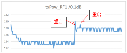
In addition, before and after the error occurred, the monitoring and alarm module was used to monitor the receiving gain and transmitting power at that time, and it was found that these radio frequency indicators were quite different before and after restarting, as shown in the figure below. What does this phenomenon indicate?

No change in temperature before and after restarting.

The receiving gain was higher after restarting.

Transmitting gain became higher after restarting.

Kind regards,

Katherine

  • Hi Katherine,

    I would like you to answer the following questions:

    • Which EVM are you using? (Assuming you have a 4-chip cascade used with mmWave Studio)
    • How are you processing the data (MATLAB example or custom postprocessing)? 
    • Is it possible for you to quantify and describe in detail the type of errors or deviation in the point cloud that you are observing?
    • Is this consistent or happens on random frames?
    • Is it possible to have plot (2D FFT) of good data vs erroneous data? To understand whether it's something to do with the data or the post processing algorithm.
    • To your second concern, can you explain the steps you followed to arrive at this? Which monitors were enabled with what configurations and what mmwavelink APIs were issued (in the same order to recreate the problem)? 

    Regards,

    Kaushik

  • Hi Kaushik,

    1. We used the AWR2243 cascade chip, a four-chip cascade board developed by ourselves

    2. We processed it in the order of 1DFFT, 2DFFT, non-coherent accumulation, speed expansion, and 3DFFT, and we used matlab for processing. The process was consistent with the MATLAB example.

    3. The errors in the point cloud were that the angle measurement was erroneous, and the speed measurement was also erroneous. We analyzed the cause and thought that the speed expansion error was caused by the change of the phase, which caused the speed angle error. The speed extension involved the MaxVelcity Extend algorithm in the AOA DPU in mmWave Studio.

    4. After the radar was started, it could run normally. Once an error occurred, all frames would be abnormal. It would not be normal again until it was reset.

    5. At present, we believed that the RD diagram after 2DFFT was not erroneous, because the phase difference between the antennas caused errors in subsequent angle measurement and speed expansion.

    6. For the second question, AWR2243 provided an API that could monitor the temperature, transmit power, receive gain, noise figure and so on of each TX and RX. We started the radar, continued to work, and recorded the changes of these indicators during the day. We found that during the day, when the temperature is high, the receiving gain would decrease and the noise figure would increase, resulting in a shorter radar detection distance. We hope that the performance of the radar during the day can be as good as that at night, or not drop so much.

    Regards,

    Katherine

  • Hi Katherine,

    Thank you for your detailed response. I would like you to answer some more questions in order to get more information about the problem at hand.

    • Can you mention your Rx Gain (dB), RF gain target and starting frequency? Hope the same is configured upon restart and doesn't get changed during the program's runtime.
    • Have you performed the calibration on the ADC data? (Refer section 4.2 in mmWaveStudio/MatlabExamples/signal_processing_4chip_cascade.pdf)
    • Is it possible to share the outputs in form of plots of AWR_MONITOR_RX_GAIN_PHASE_REPORT_AE_SB (RX_PHASE_ VALUE, STATUS_FLAGS) across devices over time (good case vs bad case)?
    • Are you performing any Rx channel gain/offset compensation?
    • Are you applying any other kind of phase corrections in your post processing?
    • Is the deviation random or is there a pattern to it (delta in m/s or radian respectively)? Would be great if you shared a plot of actual vs expected.
    • Can you confirm the same behavior with respect to the deviation when running the example code on the same ADC data? Is your post processing consistent with the VmaxExtend doppler phase correction as per the example?

    Regards,

    Kaushik