This thread has been locked.

If you have a related question, please click the "Ask a related question" button in the top right corner. The newly created question will be automatically linked to this question.

IWR6843ISK: How to change the Field of View and Range parameters in the .CFG File ?

Part Number: IWR6843ISK

Hello Experts, 

I am currently using IWR6843ISK EVM board and using Area Scanner and People Counting labs.  I want to implement my test set up in a small room for the Radar sensors by fixing them to the wall. I have few queries in modifying the .cfg files. 

Currently, I am using two labs for my data extraction. I want to test these two labs and get the localization of the objects and humans.

For object data Localization: I am using Area scanner lab with this below CFG configuration: area_scanner_68xx_ISK.cfg 

% ***************************************************************

% Created for Area Scanner v2.0.x

% Frequency:60

% Platform:xWR68xx

% Azimuth Resolution(deg):15 + Elevation

% Range Resolution(m):0.0703

% Maximum unambiguous Range(m):14.4

% Maximum Radial Velocity(m/s):2.45

% Radial velocity resolution(m/s):0.15

% Frame Duration(msec):100

% ***************************************************************


% *****************STANDARD MMWAVE SDK COMMANDS******************

sensorStop

flushCfg

dfeDataOutputMode 1

channelCfg 15 7 0

adcCfg 2 1

adcbufCfg -1 0 1 1 1

profileCfg 0 60.5 100 25 69 0 0 50 1 256 6000 0 0 30

chirpCfg 0 0 0 0 0 0 0 1

chirpCfg 1 1 0 0 0 0 0 4

chirpCfg 2 2 0 0 0 0 0 2

frameCfg 0 2 32 0 100 1 0

lowPower 0 0

guiMonitor -1 1 0 0 0 0 0

cfarCfg -1 0 2 8 4 3 0 20 0

cfarCfg -1 1 0 4 2 3 1 15 0

multiObjBeamForming -1 1 0.5

clutterRemoval -1 1

calibDcRangeSig -1 0 -5 8 256

extendedMaxVelocity -1 0

bpmCfg -1 0 0 1

lvdsStreamCfg -1 0 0 0

compRangeBiasAndRxChanPhase 0.0 1 0 1 0 1 0 1 0 1 0 1 0 1 0 1 0 1 0 1 0 1 0 1 0

measureRangeBiasAndRxChanPhase 0 1.5 0.2

CQRxSatMonitor 0 3 15 125 0

CQSigImgMonitor 0 115 6

analogMonitor 0 0

aoaFovCfg -1 -90 90 -90 90

cfarFovCfg -1 0 0 11.11

cfarFovCfg -1 1 -2.04 2.04


% *****************TRACKING COMMANDS*****************************

staticBoundaryBox -8 8 0 8 -1 2

boundaryBox -8 8 0 8 -1 2

gatingParam 4 2 2 2 10

stateParam 20 10 10 50 1

allocationParam 200 155 0.5 10 2 2

maxAcceleration 0.1 0.1 0.1

trackingCfg 1 2 250 20 20 260 100 90

% *****************STATIC DETECTION COMMANDS*********************

heatmapGenCfg -1 1  0 6 50 60.0 3.0 10

staticDetectionCfg -1 0 -50.0 +50.0 -20.0 20.0 0.7 6.0 0.2 4 20.0

% *****************SENSOR START*********************

sensorStart

 For Human data Localization: I am using 3D people counting lab with this below CFG configuration: ISK_6m_default.cfg

 ISK_6m_default.cfg from 3D people coutning lab 

% SDK Parameters

% See the SDK user's guide for more information

% "C:\ti\mmwave_sdk_[VER]\docs\mmwave_sdk_user_guide.pdf"

sensorStop

flushCfg

dfeDataOutputMode 1

channelCfg 15 7 0

adcCfg 2 1

adcbufCfg -1 0 1 1 1

lowPower 0 0


% Detection Layer Parameters

% See the Detection Layer Tuning Guide for more information

% "C:\ti\mmwave_industrial_toolbox_[VER]\labs\people_counting\docs\3D_people_counting_detection_layer_tuning_guide.pdf"

profileCfg 0 60.75 30.00 25.00 59.10 657930 0 54.71 1 96 2950.00 2 1 36

chirpCfg 0 0 0 0 0 0 0 1

chirpCfg 1 1 0 0 0 0 0 2

chirpCfg 2 2 0 0 0 0 0 4

frameCfg 0 2  96  0 55.00 1 0

dynamicRACfarCfg -1 4 4 2 2 8 12 4 8 5.00 8.00 0.40 1 1

staticRACfarCfg -1 6 2 2 2 8 8 6 4 8.00 15.00 0.30 0 0

dynamicRangeAngleCfg -1 0.75 0.0010 1 0

dynamic2DAngleCfg -1 1.5 0.0300 1 0 1 0.30 0.85 8.00

staticRangeAngleCfg -1 0 8 8

antGeometry0 0 -1 -2 -3 -2 -3 -4 -5 -4 -5 -6 -7

antGeometry1 -1 -1 -1 -1 0 0 0 0 -1 -1 -1 -1

antPhaseRot 1 1 1 1 1 1 1 1 1 1 1 1

fovCfg -1 70.0 20.0

compRangeBiasAndRxChanPhase 0 1 0 1 0 1 0 1 0 1 0 1 0 1 0 1 0 1 0 1 0 1 0 1 0


% Tracker Layer Parameters

% See the Tracking Layer Tuning Guide for more information

% "C:\ti\mmwave_industrial_toolbox_[VER]\labs\people_counting\docs\3D_people_counting_tracker_layer_tuning_guide.pdf"

staticBoundaryBox -3 3 0.5 7.5 0 3

boundaryBox -4 4 0 8 0 3

sensorPosition 1.5 0 15

gatingParam 3 2 2 2 4

stateParam 3 3 12 500 5 6000

allocationParam 40 100 0.1 20 0.5 20

maxAcceleration 0.1 0.1 0.1

trackingCfg 1 2 800 30 46 96 55

presenceBoundaryBox -3 3 0.5 7.5 0 3

sensorStart

Query 1 :  Could someone please give which of the Parameters from the CFG file are responsible to update:

  • The field of view value  to 60 Degree azimuth and 60 deg elevation? 
  • Change the Range of the Radar sensor to 2.5 meters

I have referred the MM wave SDK user guide and people counting Track layer and detection layer user guides, but it is not clear to understand which parameters in the CFG file are responsible to change the Field of the view of the sensor and range ? 

Query 2: What is the process of updating the CFG files? Is it like changing the CFG file in a notepad would work ?

Looking forward to your reply! 

Best Regards,
Shravya  

    • The field of view value  to 60 Degree azimuth and 60 deg elevation? 

    aoaFovCfg does this for the Area Scanner Lab. See the document at 

    C:/ti/mmwave_sdk_03_06_00_00-LTS/docs/mmwave_sdk_user_guide.pdf

    fovCfg does this for the people counting lab. See the document at 

    https://dev.ti.com/tirex/explore/node?a=1AslXXD__1.00.00.26&node=A__AMH81pbICLF3ScBRW5hxsA__radar_toolbox__1AslXXD__1.00.00.26

    • Change the Range of the Radar sensor to 2.5 meters

    For both labs, see our chirp design tool for this at 

    https://dev.ti.com/gallery/view/mmwave/mmWaveSensingEstimator/ver/2.1.1/

    You can design your chirp to occupy 2.5 m of range by navigating to the chirp design and tuning tab, loading your cfg with the "Load cfg" button and adjusting the chirp parameters as described here.

    https://www.ti.com/lit/an/swra553a/swra553a.pdf

    Query 2: What is the process of updating the CFG files? Is it like changing the CFG file in a notepad would work ?

    Yes you can modify them as plain text. Make sure to leave an empty line at the end of each cfg file to ensure our visualizer tools use them correctly.

    Best,

    Nate

  • Hello Nathan, 

    Thank you very much for the reply! 

    To Summarise, aoaFovCfg is for the Area Scanner and fovCfg is for the 3D people counting. 

    Other Queries: I am learning about Radar Chirps and its working principle, could you please provide elaborated brief on my below queries ? 

    •  If I am changing the Field of view of the sensor and which other Radar sensor parameters get effected  ?
    • What are the changes in Radar output I am going to see if I decrease field of view to 40 degree?
    •  If I reduce the Range to 2.5 m, what changes will i get to see in the Radar Chirps performance ? 
    • What are the ideal recommended CFG file parameters for Area scanner lab for Wall mounting and 3D people counting lab for Wall mounting, other than ideal suggestions about position?
    • Is there a command for Range parameter in CFG file ? So that I can directly change it in the text's file ? 
    • What are the differences of the Area Scanner Lab firmware to the 3D people Counting Lab Firmware, I see that they are developed on different process chain and I couldn't get deeper understanding by that, Could you please mention a brief on this, and please attach a reading document to refer the deeper understanding of this lab firmware? 
    • Is there a Tuning Guide for Area scanner Lab ? 
    • "sensorPosition" command in the .cfg file for Area scanner is missing, how exactly I have to give the sensor position to the sensor? 

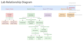
    I have a picture which explains the tree of the labs, where Can I get deeper understanding of Barlett chain and Capon Chain ?

    Looking forward for your reply, 
    Shravya 

  • Hi Shravya,

    Please ask 1 question or 1 series of closely related of questions per post. This helps us keep E2E organized for future users. If you just repost this into a few series of questions I'll be happy to assist.

    Best,

    Nate

  • Hello Nathan, 

    Thanks for the reply,  let's make this post mostly on CFG files... 

    Here are my Questions to get better understanding on the CFG files for Area Scanner and 3D people counting. 

    To Summarize, aoaFovCfg is for the Area Scanner and fovCfg is for the 3D people counting. 

    Queries: could you please provide elaborated brief on my below queries to bring more understanding on parametrization of sensor within CFG files. 

    1.  If I am changing the Field of view of the sensor in Area Scanner/3D People counting and which other sensor parameters within .cfg file of Area Scanner/3D People counting gets effected  ?
    2. What are the changes in Radar output I am going to see if I decrease field of view  "aoaFovCfg" , "fovCfg " to 40 degree?
    3.  If I reduce the Range to 2.5 m, what changes will i get to see in the Radar Chirps performance ? 
    4. What are the ideal recommended CFG file parameters for Area scanner lab for Wall mounting and 3D people counting lab for Wall mounting, other than ideal suggestions about position?
    5. Is there a command for Range parameter in CFG file ? So that I can directly change it in the text's file ? 
    6. Is there a Tuning Guide to understand the .cfg file for Area scanner Lab ? 
    7. "sensorPosition" command in the .cfg file for Area scanner is missing, how exactly I have to give the sensor position to the sensor

    Here are the Queries which are based on CFG file configuration, Hope this Query makes a filtered one. 

    Looking forward to your valuable feedback. 

    Best Regards,
    Shravya 

    •  If I am changing the Field of view of the sensor in Area Scanner/3D People counting and which other sensor parameters within .cfg file of Area Scanner/3D People counting gets effected  ?

    No other parameters should be affected by this change

    • What are the changes in Radar output I am going to see if I decrease field of view  "aoaFovCfg" , "fovCfg " to 40 degree?

    You will no longer detect points outside of the 40 degrees. This change is at the detection layer so no other changes should be seen.

    •  If I reduce the Range to 2.5 m, what changes will i get to see in the Radar Chirps performance ? 

    Reducing the range will increase the range resolution for a finite number of range bins. No other changes should be seen.

    What are the ideal recommended CFG file parameters for Area scanner lab for Wall mounting and 3D people counting lab for Wall mounting, other than ideal suggestions about position?

    There is no one ideal cfg. The performance will depend on the conditions the device is placed in. You can consult the people counting detection layer and tracker layer tuning guides for information on how to tune for your situation.

    https://dev.ti.com/tirex/explore/node?a=1AslXXD__1.00.00.26&node=A__AODg1wot4.WiFsu-spZhtQ__radar_toolbox__1AslXXD__1.00.00.26

    • Is there a command for Range parameter in CFG file ? So that I can directly change it in the text's file ? 

    You cannot set the range directly, but you can refer to my previous answer about reducing the range and yes you can directly change it in the text's file.

    • Is there a Tuning Guide to understand the .cfg file for Area scanner Lab ? 

    You can see the SDK tuning guide at C:/ti/mmwave_sdk_03_06_00_00-LTS/docs/mmwave_sdk_user_guide.pdf  and the tracker layer tuning guide for people coutning referenced above.

    1. "sensorPosition" command in the .cfg file for Area scanner is missing, how exactly I have to give the sensor position to the sensor

    This feature is not implemented in the Area Scanner lab. you can implement it yourself if you want to