This thread has been locked.

If you have a related question, please click the "Ask a related question" button in the top right corner. The newly created question will be automatically linked to this question.

IWR1843BOOST: Tx phase shift per chirp

Part Number: IWR1843BOOST
Other Parts Discussed in Thread: IWR1843

Hello,

Using the IWR1843 Demo code that comes with SDK 3.5.0.4, I want to change the transmission phase for each chirp as shown below.

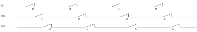
It seems that it can be achieved by using subFrame, but there is a constraint of InterBurstBlankTime (min 500us?), and I am looking for a way to shorten the chirp interval as much as possible.

Please let me know if there is a better way to achieve transmission phase switching.

Best Regards,

Hiroyuki Taguchi

  • Hi,

    Can you use the TXPhaseShifter argument? You could make two profileCfg lines and include them both in a single chirpCfg line in the configuration file. Based off https://www.ti.com/lit/an/swra553a/swra553a.pdf, you should only need 50 usec between bursts, not 500 msec. Where do you see that number?

    Best,

    Nate

  • Hi Nate,

    Thank you for your reply.

    >You could make two profileCfg lines and include them both in a single chirpCfg line in the configuration file.

    I will check this setting method.

    >you should only need 50 usec between bursts, not 500 msec. Where do you see that number?

    I saw in the comments the member variable rlUInt32_t burstPeriodicity of the typedef struct rlSubFrameCfg in the SDK's header file below.

    mmwave_sdk_03_05_00_04/packages/ti/control/mmwavelink/include/rl_sensor.h

    /**
    * @brief burstPeriodicity >= (numLoops)* (sum total of all unique chirp times per burst) +
    InterBurstBlankTime, \n
    where InterBurstBlankTime is primarily for sensor calibration / monitoring, \n
    thermal control, and some minimum time needed for triggering next burst. \n
    InterBurstBlankTime >= 100 us. Refer a NOTE at end of this API for more info. \n
    With loop back enabled, InterBurstBlankTime >= 500 us \n
    @note : Across bursts, if the value numOfChirps, is not a constant, then the \n
    actual available blank time can vary and needs to be accounted for \n
    1 LSB = 5 ns \n
    */

    Best regards,

    Horoyuki

  • Hi Nate,

    >You could make two profileCfg lines and include them both in a single chirpCfg line in the configuration file.

    I tried setting multiple profiles, but I don't know how to set them.

    Please tell me how to set with SDK 3.5.0.4 CLI command.

    And, SDK 3.5.0.4 User Guide
    mmwave_sdk_03_05_00_04/docs/mmwave_sdk_user_guide.pdf
    profileCfg command profileId argument description says:

    Legacy frame
    (dfeOutputMode=1): could be
    any allowed value but only
    one valid profile per config is
    supported
    Advanced frame
    (dfeOutputMode=3): could be
    any allowed value but only
    one profile per subframe is
    supported.
    subframes can have different
    profiles

    Is it possible to use multiple different profiles within one frame or subframe?

    What I want to achieve is to switch the transmission phase for each chirp, as shown in the thread's first figure.

    Best regards,

    Hiroyuki

  • Hi Hiroyuki,

    I do not believe that you need to use the subframes here. I think you can achieve what you're looking for by declaring two profileCfg lines and adding them to the same chirpCfg. Below is my best approximation of what you could do. I started with the profile_2d.cfg file located in C:\ti\mmwave_sdk_03_06_00_00-LTS\packages\ti\demo\xwr68xx\mmw\profiles and I've commented to indicate the relevant changes. This exact chirp profile is untested, but the methodology is how I would recommend designing your chirp.

    %o degree phase shift chirp (default)
    profileCfg 0 60 7 3 24 0 0 166 1 256 12500 0 0 158
    %create a chirp with 180 degree phase shift because 8421504 = 0b00000000100000001000000010000000. See link for more details.
    profileCfg 1 60 7 3 24 0 8421504 166 1 256 12500 0 0 158
    %add a 70 usec delay before the first chirp
    profileCfg 2 60 70 3 24 0 0 166 1 256 12500 0 0 158
    %add a 70 usec delay before the first chirp with phase shift
    profileCfg 3 60 70 3 24 0 8421504 166 1 256 12500 0 0 158
    
    %chirp pattern is 0 degrees + long delay, 0 degrees, 0 degrees, 180 degrees + long delay, 180 degrees, 180 degrees
    %0 degrees + long delay
    chirpCfg 0 0 2 0 0 0 0 1
    %0 degrees
    chirpCfg 1 1 0 0 0 0 0 2
    %0 degrees
    chirpCfg 2 2 0 0 0 0 0 4
    %180 degrees + long delay
    chirpCfg 3 3 3 0 0 0 0 1
    %180 degrees
    chirpCfg 4 4 1 0 0 0 0 2
    %180 degrees
    chirpCfg 5 5 1 0 0 0 0 4
    % do chirps 0-5 in succession
    frameCfg 0 5 32 0 100 1 0

    Best,

    Nate

  • Hi Nate,

    I created the following configuration file based on the information you provided and tested it, but an error is returned after sensorStart.

    mmwDemo:/>sensorStart
    Debug: Init Calibration Status = 0x1ffe
    Error -1

    Firmware used in testing: mmwave_sdk_03_06_00_00-LTS/packages/ti/demo/xwr18xx/mmw/xwr18xx_mmw_demo.bin

    Am I doing something wrong?

    Is it possible to test the operation?

    sensorStop
    flushCfg
    dfeDataOutputMode 1
    channelCfg 15 7 0
    adcCfg 2 1
    adcbufCfg -1 0 1 1 1
    lowPower 0 0
    %o degree phase shift chirp (default)
    profileCfg 0 77 7 3 24 0 0 166 1 256 12500 0 0 30
    %create a chirp with 180 degree phase shift because 8421504 = 0b00000000100000001000000010000000. See link for more details.
    profileCfg 1 77 7 3 24 0 8421504 166 1 256 12500 0 0 30
    %add a 70 usec delay before the first chirp
    profileCfg 2 77 70 3 24 0 0 166 1 256 12500 0 0 30
    %add a 70 usec delay before the first chirp with phase shift
    profileCfg 3 77 70 3 24 0 8421504 166 1 256 12500 0 0 30
    %chirp pattern is 0 degrees + long delay, 0 degrees, 0 degrees, 180 degrees + long delay, 180 degrees, 180 degrees
    %0 degrees + long delay
    chirpCfg 0 0 2 0 0 0 0 1
    %0 degrees
    chirpCfg 1 1 0 0 0 0 0 2
    %0 degrees
    chirpCfg 2 2 0 0 0 0 0 4
    %180 degrees + long delay
    chirpCfg 3 3 3 0 0 0 0 1
    %180 degrees
    chirpCfg 4 4 1 0 0 0 0 2
    %180 degrees
    chirpCfg 5 5 1 0 0 0 0 4
    % do chirps 0-5 in succession
    frameCfg 0 5 32 0 100 1 0
    guiMonitor -1 1 1 1 0 0 1
    cfarCfg -1 0 2 8 4 3 0 15.0 0
    cfarCfg -1 1 0 4 2 3 1 15.0 0
    multiObjBeamForming -1 1 0.5
    calibDcRangeSig -1 0 -5 8 256
    clutterRemoval -1 0
    compRangeBiasAndRxChanPhase 0.0 1 0 1 0 1 0 1 0 1 0 1 0 1 0 1 0 1 0 1 0 1 0 1 0
    measureRangeBiasAndRxChanPhase 0 1. 0.2
    aoaFovCfg -1 -90 90 -90 90
    cfarFovCfg -1 0 0.25 8.64
    cfarFovCfg -1 1 -10.59 10.59
    extendedMaxVelocity -1 0
    CQRxSatMonitor 0 3 11 121 0
    CQSigImgMonitor 0 127 8
    analogMonitor 0 0
    lvdsStreamCfg -1 0 0 0
    calibData 0 0 0
    sensorStart
    

    Best,

    Hiroyuki

  • Hi,

    Apologies for the confusion. The cfg shown above was not meant to be an exact working snippet. It was just meant to illustrate the changes described. You can put your device in debug mode to find the source of the error. I would be willing to bet it has to do with the timing of the frameCfg.

    https://dev.ti.com/tirex/explore/node?a=1AslXXD__1.00.00.26&node=A__AKZl2I1OiS5ssBNGpidsCQ__radar_toolbox__1AslXXD__1.00.00.26

    Best,

    Nate

  • Hi Nate,

    Thank you for your reply.

    Try to trace the cause of the error with the debugger.

    I will close this matter for now.

    Thanks,

    Hiroyuki