Other Parts Discussed in Thread: TUSS4470
Hi,
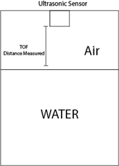
I would like to implement a system to measure the distance between the sensor and the water level in a tank using TDC1000 and a 10mm ultrasonic sensor with Fc = 300Khz. As in the following sketch:
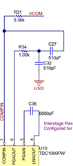
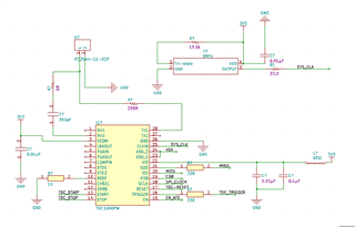
I have this circuit on my PCB:
 And I wrote some code and configured the registry parameters as follows:
CONFIG_0
RAW: 0x86
TX_FREQ_DIV: 32
NUM_TX: 6
CONFIG_1
RAW: 0x40
NUM_AVG: 1
NUM_RX: 0
CONFIG_2
RAW: 0x0
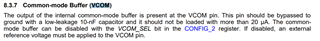
VCOM_SEL: INT
MEAS_MODE: TOF
DAMPING: OFF
CH_SWP: OFF
EXT_CHSEL: OFF
CH_SEL: 1
TOF_MEAS_MODE: 0
CONFIG_3
RAW: 0x4
TEMP_MODE: REF, RTD1, RTD2
TEMP_RTD_SEL: PT1000
TEMP_CLK_DIV: 8
BLANKING: OFF
ECHO_QUAL_THLD: -220 mV
CONFIG_4
RAW: 0x1F
RECEIVE_MODE: SINGLE ECHO
TRIG_EDGE_POLARITY: RISING
TX_PH_SHIFT_POS: 31
TOF_1
RAW: 0x24
PGA_GAIN: 3 dB
PGA_CTRL: ON
LNA_CTRL: ON
LNA_FB: RESISTIVE
TIMING_REG[9:8]: 0
TOF_0
RAW: 0x0
TIMING_REG[9:0]: 0
ERROR_FLAGS
RAW: 0x0
ERR_SIG_WEAK: 0
ERR_NO_SIG: 0
ERR_SIG_HIGH: 0
TIMEOUT
RAW: 0x4C
FORCE_SHORT_TOF: ON
SHORT_TOF_BLANK_PERIOD: 16 x T0 -> 2.00 us
ECHO_TIMEOUT: OFF
TOF_TIMEOUT_CTRL: 128 x T0 -> 16.00 us
CLOCK_RATE
RAW: 0x0
CLOCKIN_DIV: 1
AUTOZERO_PERIOD: 64 x T0 -> 8.00 us
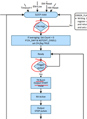
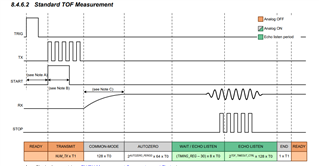
TOF Control: Short TOF
Common-mode: 16.00 us
Autozero: 8.00 us
Transmit: 24.00 us
Mask/Blank: 2.00 us
Echo listen: 16.00 us
End: 4.00 us
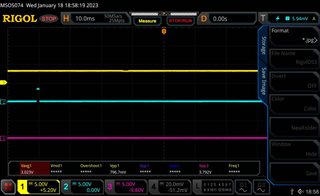
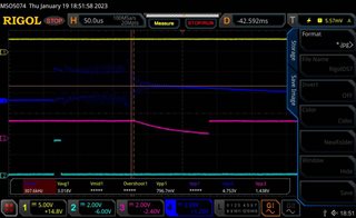
But I can't get a pulse on TX pin or RX_pin
I configure the TDC1000 with the indicated parameters, I change the EN_pin to high, I make high and low on the trigger pin. But the only thing I have is the infinitely high TX_pin. (I don't have a pulse similar to the datasheet example).
I don't understand what I could be doing wrong.

best regards
Daniel Pozzatti