This thread has been locked.

If you have a related question, please click the "Ask a related question" button in the top right corner. The newly created question will be automatically linked to this question.

TUSS4440: Schematic review

Part Number: TUSS4440
Other Parts Discussed in Thread: TUSS4470

Dear team, 

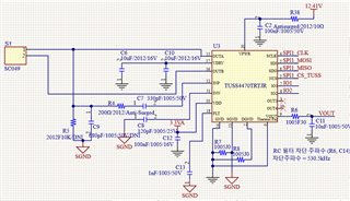
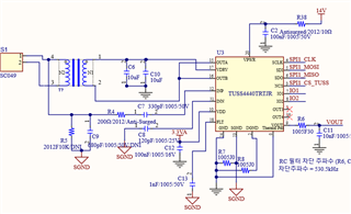
Please review below customer schematic and let  me know your opinion. 

<Customer specification> 

- HALF_BRG_MODE=1

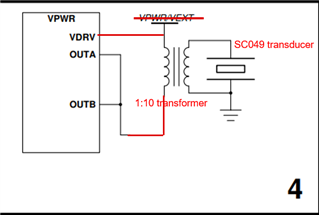
- No center tap transformer 

     => UA7868: https://www.coilcraft.com/getmedia/68859f8a-dc69-4e19-a712-980f2bf1066e/ua7868.pdf

- VPWR : 12.4 ~ 16V , VDRV : 13V

- Frequency : 390~510KHz 

- Transducer 

     => SC049: https://www.seco-sensor.de/wp-content/uploads/2021/07/DB049-A.pdf

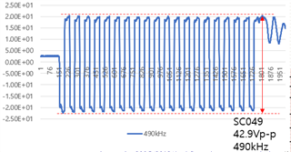
- Expected driving transducer voltage : up to 160V

- Expected sensing distance : 250mm 

<Customer schematic> 

Thank you. 

  • Hey Dino,

    Thanks for posting to the sensing forum! I wont be able to perform this schematic review today but I will get back to you on Monday with any notes I may have. Thanks for the patience here!

    Best,

    Isaac

  • Hey Dino,

    Thanks for the patience on this. I was able to review the schematic as well as all the comments you posted.

    1. Frequency : 390~510KHz  and transducer SC049: https://www.seco-sensor.de/wp-content/uploads/2021/07/DB049-A.pdf
      1. The frequency of this transducer is rated at 490kHz while the TUSS4440 is only rated for 400kHz. I don't think this is a good matchup. If the customer is interested in using this transducer then my recommendation would be to look at TUSS4470 which is capable of running at 1MHz. 
    2. Expected sensing distance : 250mm
      1. Is this the max distance that the customer is going to measure? The 160V driving voltage sounds really high for such a small range.
    3. INN pin
      1. I see a 120pF capacitor here but based on the frequency the recommended starting point would be 8-9nF. The customer can tune this capacitor value as needed. I have attached the formula below:
    4. INP pin
      1. These components may require additional tuning when they are in  the final board and the final transducer is chosen.
    5. VOUT filter
      1. This filter may not be necessary there are already internal filters to help eliminate possible noise at the output, customer can try running without the filter to see if its necessary.

    My main concern is the frequency of the transducer. Since the frequency is 490kH this is significantly past the devices range.

    Please let me know if there are any questions or comments.

    Best,

    Isaac

  • Hello Isaac, 

    Thank you for your comment. 

    Originally, the customer would like to use TUSS4470 with SC049 transducer as below schematic. 

    But Max distance is about 191mm under VDRV :20V so the customer want to use transformer to make over 100Vp-p. As mentioned above, Max Expected sensing distance is 250mm. But due to product size issue, they can not use center tap transformer. The best option of transducer is SC049.

    Please let me know your opinion or recommendation regarding below question.  

    1. Using TUSS4470, Is there any solution to increase sensing distance? 
        => The customer think that they need about 100Vp-p for 250mm sensing distance 
        => To use trnasformer(no-center tap), Should we use HALF-BRG_MODE=1? 

    2. If the customer use HALF-BRG_MODE=1(Case 4) of TUSS4470 ,external power source and external FET are mandatory option? 
        => What is current limit for Internal FET? 
        => If external FET is mandatory option, TUSS4470 is used pre-driver mode(Max440KHz). Is it right? 
        => Is it possible to use below concept using TUSS4470 and SC049 transducer for 250mm sensing distance? 

    Thank you. 

  • Hello Dino,

    Thanks for the info. TUSS4470 in order to generate 100Vpp would need to be driven differently and not using its direct drive mode since VDRV can only be setup to 36V so able to generate approximately 72Vpp compared to the 100Vpp the customer is seeking.

    To use a single-ended transformer (transformer with no center tap) then HALF_BRIDGE_MODE = 1, this setting allows the user to drive both low side and high side FETs together.

    I am not sure what the current output limits are on the internal FETs but I am assuming the external FET is required because the OUTA and OUTB pins might not able to source the current required to drive the transformer properly, hence PRE_DRIVER_MODE =1 which allows the user to drive external FETs to provide the current necessary for the transformer. But using this option would limit the user to the 440kHz, which is a slight improvement from the 400kHz limitation in TUSS4440.

    I can check with design team internally with the team how much current the internal FETs can provide using OUTA and OUTB, if this value is enough then they might not require using the pre-driver mode to drive the external FETs and use a topology to what you drew on case 4 might be possible.

    I will check back with you once I get a response from the design team.

    Best,

    Isaac

  • Hello Isaac, 

    Thank you for your strong support. 

    When can I get feedback regarding the current capability of the internal FETs?

    The customer have to use SC049 transducer for 250mm sensing distance and they can not use 36V supply due to board size issue(8x50mm).

    The only option is TUSS4470 + no center tap transformer + SC049 transducer. 

    Please let me know your opinion or recommendation regarding this issue. 

    Thank you.  

  • Hello Dino,

    Always glad to help out. I am still pending the response from the design team I will ping them again regarding any updates on the request.

    I will get back to you as soon as I get some input from the team, I appreciate the patience here.

    Best,

    Isaac

  • Hey Dino,

    Just a quick update. I just got a design team member assigned to review this for us so hopefully it should not be too long before I get a response over to you.

    Thanks for the patience!

    Best,

    Isaac

  • Hello Isaac, 

    Is there any update on this request? 

    Thank you. 

  • Hello Dino,

    No update on this yet. Let me ping the design team on this. 

    I am out visiting a customer tomorrow so I may not be able to get back to you until Thursday. Thanks for your patience!

    Best,

    Isaac

  • Hello Dino,

    Sorry for the delay on this one, I spoke to the design team today. Internally the topologies are different for both the devices. My main concern was the current limitations on what the devices can handle, but it seems max current that can come back into the system is very similar.

    My suggestion would be if the customer has a setup with the TUSS4440, as shown in setup image 4, they can easily replace with TUSS4470 and run the test with that setup to see if the device is able to drive the transformer properly. Since the devices have the same pinout it should be very easy for them to perform this swap. Just keep in mind it could be possible they damage the device or the transformer if the test is not successful.

    Best,

    Isaac