This thread has been locked.

If you have a related question, please click the "Ask a related question" button in the top right corner. The newly created question will be automatically linked to this question.

IWR6843ISK: Max Frame Speed for measuring velocity of small targets

Part Number: IWR6843ISK

Hi there,

I'm working on a project that's looking at detecting the velocity of a falling object over about 4m. The overarching question is how to get the best velocity read rate and velocity accuracy of a single target.
This object should be the only moving object in view of the radar unit which should mean that velocity resolution shouldn't be that important (question, I'm not 100% sure about that), it does have a very small RCS (~0.0005m²).
I have been able to see the object but the rate of measurement or the quantisation of the velocity has given me a rougher view of the velocity than I would like.

Related to the overarching question, what does the number of chirp loops variable control? I don't understand this.
Is there a way to control the number of doppler bins? I see a counter for them in the mmWaveSensingEstimator but I'm not sure if this is actually manually adjustable?

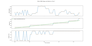
I've attached a plot I've produced from my prior testing if this helps with understanding what I mean. I have also attached the .cfg file that I have been using.  

4_3_Doppler_dB_down_xwr68xx_profile_2023_01_15T22_29_24_331 - Copy.cfg 

Many thanks,

Aston

  • Hi Aston,

    In general, the way you'll get a better measurement of velocity in your scenario is by taking more samples of velocity, which is by increasing the number of chirps per frame. You can do this by increasing the numLoops variable in frameCfg.

    As you increase the number of loops, the number of doppler bins will automatically increase too (typically by next largest power of 2 that comes after the number of loops e.g. 20 loops -> 32 doppler bins).

    You could also artificially improve your accuracy by zero-padding your doppler FFT. Depending on which demo you're using as a starting point, you'll be doing a doppler FFT on the HWA or the DSP. See the documentation here for how to zero-pad in your specific use case.

    C:/ti/mmwave_sdk_03_06_00_00-LTS/packages/ti/datapath/dpc/dpu/dopplerproc/docs/doxygen/html/index.html

    To do this, you may have to modify the src code though (not the cfg which is what you were modifying above).

    Best,

    Nate

  • Hi Nathan,

    When I open the config file above in the TI Demo Visualizer it seems to suggest that it does 60 chirp loops rather than the specified (in that config file) 20 chirp loops. I wonder if there are any other parameters that affect the number of chirp loops?

    I've also been playing around with the online chirp creation tool, but the couple of chirps I have created (which haven't shown any failures using the chirp creation tool) all seem to have overloaded when I try to put them onto the radar unit. i.e. the radar unit seems to load them but then gets locked up and doesn't send any data. Attached below for reference.

    5_1_profile_2023_01_26T03_35_27_848.cfg

    Is there a document that simply (for people still learning about Radar and the data processing used) explains the different components of the radar config and the customisation possibilities, or is that information found in a variety of places and I just need to do further reading to understand the possible customisation options?

    Thanks,

    Aston

  • Hi Aston,

    I think the discrepancy you're seeing here is because you have three chirps in a loop, and you're looping then 20 times (60 chirps total). Take a look at the SDK user's guide for a more detailed description of each parameter.

     C:/ti/mmwave_sdk_03_06_00_00-LTS/docs/mmwave_sdk_user_guide.pdf

    To learn why this particular chirp fails, you will need to put the device in debug mode and read the error message. See this guide for the procedure.

    https://dev.ti.com/tirex/explore/node?a=1AslXXD__1.00.00.26&node=A__AKZl2I1OiS5ssBNGpidsCQ__radar_toolbox__1AslXXD__1.00.00.26

    Best,

    Nate

  • Hi Nathan,

    Apologies, I worked at this for a while then shifted my focus to changing the chirp/profile from repeating frames quickly into one that has a greater number of chirps per frame. This has given me chirp that gives me a much greater range accuracy, but I understand the systems range and doppler accuracy are affected by the interbin resolutions. I believe that I found the equations which define this relationship here https://e2e.ti.com/support/sensors-group/sensors/f/sensors-forum/873304/iwr6843-mmwave-sensing-estimator-discrepancies  but when I go back to calculate these numbers I realised I didn't take note of the number of FFT bins (from the sensing estimator) and as I cannot remember the specific parameters that I used for the sensing estimator.
    Is there an equation for the number of FFT bins used?

    Thanks,

    Aston

  • Hi Aston,

    The number of bins used in the range FFT can be calculated from the numAdcSamples argument of the profileCfg. Finding the next highest power of 2 greater than the numAdcSamples should be the number of bins used in the Range FFT.

    The number of bins used in the doppler FFT should be the next highest power of 2 greater than the numLoops variable in the subFrameCfg. Remember that this may not be the same as the number of chirps coming off the device because the doppler FFT compares successive chirps for the same TX/RX antenna pair, so if you have 12 virtual antennas on the IWR6843ISK device, and each transmit antenna chirps say 20 times (3 TX antennas -> 60 total chirps), then you will still do a 32 point Doppler FFT because you will only have 20 samples from each TX/RX pair, and 32 is the next multiple of 2 higher than 20. You will be left with twelve 32-point doppler FFT's at this point, which will need to be combined later in your processing chain.

    Best,

    Nate

  • Hi Nate,

    Thanks for your help, you can mark this thread as complete/solved.


    Thanks,

    Aston