Other Parts Discussed in Thread: FDC2214
Hi,
I am current trying use this fdc2214evm for a high sampling ratio capacitance sensing work, over 1000hz (T_sample= 1e-3 s), single channel.
As the given GUI can only have 30hz writing log speed without time output, I attempt to use python based on some predecessors' work, and the test sensor now is the build-in capacitor sensor on evm module.
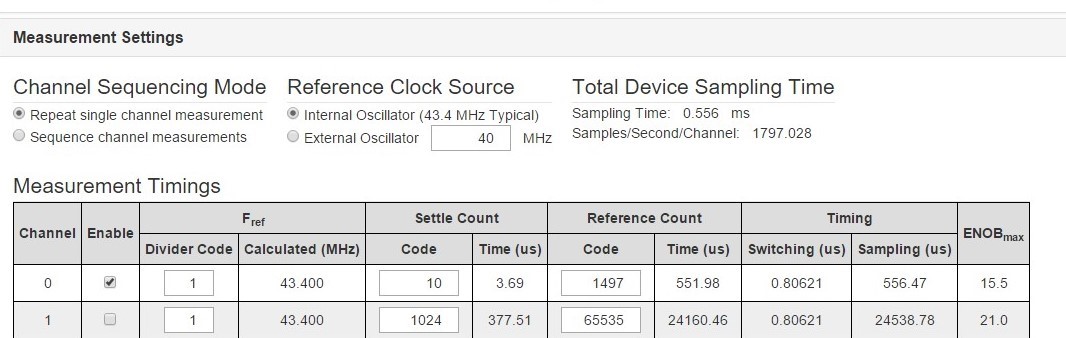
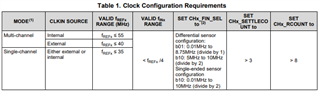
To control the sampling rate, from the example on the datasheet, the RCOUNT_CH0 and SETTLECONUT_CH0 register are related to control the conversion time and settle time (channel switching delay is treated as solid, 1 us)
SETTLECONUT_CH0 >Vpk * f_REF0 * C * pi^2 / (32 * IDRIVE0), as the Vpk is at the range of 1.2 to 1.8 (in datasheet), f_REF0 uses the internal clock (40Mhz?), the calculated SETTLECONUT_CH0 would always be smaller than 8, and select 10 for some system clearance, so that the register value is 0x000A
And also we have the settle time ts=SETTLECONUT_CH0 *16 / f_REF0= 4us
so the ideal conversion time tc should be set as (1e-3 - 1us -4us) = 5.99 e-4 s, as tc = 16* RCOUNT_CH0 / f_REF, the decimal RCOUNT_CH0 = 1497, and the register value should be 0x05D9
Besides, the CLOCK_DIVIDERS_CH0 = 0x1001
MUX_CONFIG=0x020D, CONFIG=0x1C01 for single CH0 repeat scanning.
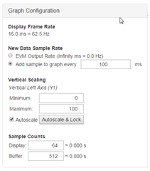
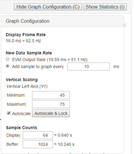
I only make these change in register via python, and I can see this values all have been changed via GUI configuration interface, but once I start the loop, the logging data would always be collect with 100hz, if it is due to my computer limit, after I change the sampling ratio to 50 hz, the logging data frequency still has no different.
It looks even I change the register values, I cannot shift this evm board sampling rate, and the sample ratio from the python is always 100hz, or probably I missed any CLOCK settings? Can you give me some suggestions?
following pic is the GUI screenshot after I run the code in Python, to show the register does been re-write