This thread has been locked.

If you have a related question, please click the "Ask a related question" button in the top right corner. The newly created question will be automatically linked to this question.

AWR2243: Rx channel phases between power cycles are Arbitrary

Part Number: AWR2243

Hi, 
We're using a custom cascade RF board which is designed as per the guidelines given by TI to design a 4-chip cascade board. 

We're using mmwave studio to collect data and as per this guide (https://www.ti.com/lit/an/spracv2/spracv2.pdf), we have generated a calibration file in a clean environment for each board(TI cascade board and custom cascade board board) and we're restoring it after configuring the board to capture data. 

We have a corner reflector kept at boresight, outside the far field distance, in front of the radar. We're capturing data through mmwave studio, power cycling the radar, and capturing it again after configuring it and restoring the calibrations. This sequence is repeated 10 times. The first 3 frames are ignored, as per guidelines and the 6th frame is plotted for each file, which has 10 frames in total. The same configuration and capture LUA script are used for both boards. 

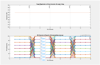
This photo shows how the phases look when we use the cascade board

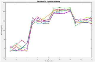
This one shows the Rx phase for our board

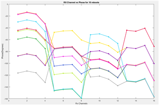
As you can see, the phases between reboots with the TI cascade board, although varying, are following a pattern. But from the custom board, it looks to be all over the place. 

Can you please help me figure out the answer to these questions?
1. Is there a step that we're missing in mmwave studio, regarding initialization and calibration? We're using the LUA files supplied by mmwave studio. The only difference is that the chirp profile is different. 

2. Have you guys seen these seemingly random phase jumps between power cycles? Any tips on why the phase between AWR chips is spread out across this big range? What can we do to prevent/minimize it? 

3. In the first photo, why does the phase of RX channels from any one AWR seems to change upon every reboot?

4. The phases of the Rx channels, for a single target at boresight, should ideally be the same, but it's not. is this expected?

We have gone through this guide (https://www.ti.com/lit/an/spracf4c/spracf4c.pdf), the guide mentioned above, and the APIs in the ICD regarding cascade calibration so far. Please let us know if there's any other reference material I missed. 
Any and all help would be greatly appreciated. 

  • Hi,

    Unfortunately the team that developed the TI cascade board is no longer available for support.

    Please give me some time to check for feedback with extended team

    thank you

    Cesar

  • I'm the HW engineer on Asher's post. I would like to add that our custom board is for all practical purposes the same design as the Cascade. We have changed the antenna configuration but the clocking, syncing, and power is unchanged. We had the design, schematic and layout, reviewed by TI with only minor changes related to pull up/down resistors and changed out an inductor to match the cascade design. The frame sync signals have been length matched and reviewed by an oscilloscope. The LO signal has also been laid out in accordance with the TI guidelines and must be working because we get coherent transmissions from all 4 AWRs.

  • Hi,

    The feedback I have received is that TI has not seen similar behavior during cascade board development.

    That being said,

    Usually the phase after reboot is not an issue, usually we care about the phase consistency overtime after booting.

    Are you using the same firmware version on both boards?

    Thank you

    Cesar

  • Hi Cesar. 

    Are you using the same firmware version on both boards?

    Yes we're using mmwave DFP 2G obtained from here (https://www.ti.com/tool/MMWAVE-DFP)

    Usually the phase after reboot is not an issue, usually we care about the phase consistency overtime after booting.

    Do you mean if we keep collecting data over time and not power cycle the radar in between, the phases between the RX should stay the same? 
    Yes, we do see it. However, it drifts by a few degrees over the course of a few hours. 

    Can you please elaborate on what you mean by phase after reboot is not an issue? If we're restoring a boot-time calibration file, shouldn't the phases between different AWRs stay the same, for the same scenario and ambient temperature conditions? 

    Please advise us as to how to solve this issue. Would the monitoring APIs such as RX loopback testing shed some light on the topic? Or any other area we can explore to troubleshoot this issue?

    Thanks

    Asher

  • HI,

    Please give me a few days to review this

    thank you

    Cesar

  • Thank you, Cesar

  • Hi,

    You may be already familiar with this document

    Cascade Coherency and Phase Shifter Calibration

    Here is some background on calibration

    The AWR2243 can be configured to perform

    • one time boot calibration
    • periodic run time calibrations

    For cascaded systems these can't be used.

    Following is a summary of the above document.

    Cascaded AWRx device phase coherency refers to the necessary factory calibration steps, run-time calibration steps and host processor routines, which must be executed to ensure that all cascaded AWRx devices maintain a known, and predicatable, temperature compensated, RX and TX phase relationship throughout runtime. The basic problem is that when dealing with multi-device, cascaded AWRx systems, the run-time calibrations built into the AWRx devices can no longer be used to update the boot-time calibrations. This is due to the run-time calibration on each device independently switching to different temperature compensated gain settings. The temperature thresholds across the multie-device system cannot be guaranteed to change at the same time. This results in temperature calibration values of different temperature bins being present on different devices, resulting in uncalibrated phase/gain relationships across the multi-device virtual channels. Also, due to the inherent “jitter” associated with the boot-time calibrations, cascaded systems can be observed to resolve to slightly different boot-time calibration values, again, resulting in inconsistent gain/phase relationships even at boot-time.


    To deal with these run-time and boot-time calibration problems a few key changes are made compared to the single-device factory calibration procedure:

    1. All run-time calibration on the cascaded AWRx devices is disabled through firmware API calls
    2. All boot-time calibration on the cascaded AWRx devices is disabled through firmware API calls
    3. Factory calibration process is expanded to also include saving boot-time and run-time temperature dependent calibration register values
    4. The host processor is tasked with reloading these boot-time calibration register values on each reset/power cycle of the AWRx system
    5. The host processor is tasked with reloading these run-time calibration register values on pre-determined operating temperature boundaries
    6. The host processor is tasked with using temperature dependent TX phase-shifter and Virtual Channel Gain/Phase calibration values based on currently loaded run-time calibration values

    Thank you

    Cesar

  • Hi, 
    Yes, you are right. We're familiar with this document and have followed the steps that you have summarized here, even then we see these jumps. 

    I was looking up monitoring reports, and there was a post in this forum( I cannot locate the URL), it mentioned the monitoring reports generated by the device through mmwave studio are not 100% accurate but they are within some tolerances. Can you please share those tolerance numbers? I want to go through those reports to search for a clue for this problem. 

    Also, is there anything else we can look at to try to diagnose this issue? 
    Thank you for your help so far

    Asher

  • Hi,

    So when you boot the device to perform the measurements are the calibrations read from a file?

    Can you please provide more details on how you ready the phase?

    Thank you

    Cesar

  • So when you boot the device to perform the measurements are the calibrations read from a file?

    Yes, 

    At first, all the boot-time calibrations are enabled, and the radar is made to go through the rf_init cycle, which executes these calibrations on boot and generates 4 binary files(1 for each AWR) which are stored in NVM. The radar is made to chirp, and ADC data is captured of a Corner reflector kept at boresight at the far field. The calibration binary files generated are parsed to ensure the status bits are all set to 1, indicating successful calibration. 

    For subsequent reboots(or power cycles), all the boot time calibrations are disabled(as advised by the ICD), and the binary files are fed back to the AWRs before rf_init. The AWRs "restore" the calibration files and proceeds to chirp. 

    We collect ADC data again and compare the phase difference between the receivers, and between power cycles. As you see in the photo I posted above, after every 4 receivers the phase jumps randomly, meaning the 4 AWRs chips are not synchronized with each other. 

    Can you please provide more details on how you ready the phase?

    I'm not sure I understand, can you please elaborate more on this? 

    Thanks 

    Asher

  • Hi Cesar, do you have any insights on this issue? 
    Any clues are greatly appreciated.

    Thanks

    Asher

  • Further updates on this thread

    Phase shifters are not used in this application. So there is no phase shifter calibration needed.

    thank you

    Cesar

  • Hi Cesar, 


    We found some more insights on the issue that I'm sharing in the hopes that it helps you guys tell us where to look, to solve this problem. 

    We enabled test source, and simulated a target at 0,10,0(x,y,z) with no velocity to it. We collected a few frames of data and rebooted. We repeated this 100 times, then we plotted the phase of the simulated target at the Rx channels between each reboot. 

    We're seeing 2 things

    1. Even for a simulated target, the phase jumps still exist. If we're correct in understanding that the test source generates a baseband which is then digitized by the ADCs and then captured, we can safely rule out the involvement of any mmwave RF circuitry. 

    2. As you see in the photo, if we plot the phase of the target between 100 reboots(power cycle- capture data- power cycle), they fall neatly into these 8 bins, which are exactly 13.9143 degrees apart. 13.9143 degrees for a target at 10 meters corresponds to a sample delay or a sample loss of exactly 1. So we can safely assume that upon each reboot, all of the AWRs are delaying the ADC sampling by a multiple of ~44ns, up to 44*8 nanoseconds ( ADC sample rate is 22.5 MHz), or if that's perfect then after digitizing, up to 8 samples are lost somewhere.

    What could cause this? Can we probe the signal on the board that enables the ADC to make sure they're reaching the AWR chips on time? Can we enable something in the CSI2 driver that can give us information about missing samples?

    I hope this information rings a bell. 

    Best

    Asher

  • Hi Cesar, did you find more insights on this problem?

    Asher

  • This issue has been narrowed down to a CSI transmission issue.

    Closing this thread

    thank you

    Cesar