This thread has been locked.

If you have a related question, please click the "Ask a related question" button in the top right corner. The newly created question will be automatically linked to this question.

OPT3101-SDK: Register configuration in dealiasing mode

Part Number: OPT3101-SDK
Other Parts Discussed in Thread: OPT3101

Dear Sir,

Since our last question consultation(OPT3101-SDK: Design questions about OPT3101... - Sensors forum - Sensors - TI E2E support forums) has been closed for a timeout, here is another consultation.

The following are the main problems that we have not yet solved.

[PROBLEM-1]

The descripton of "1447.OPT3101-Dealiasing.pdf(download from [FAQ] OPT3101: Dealias Operation - Sensors forum - Sensors - TI E2E support forums)" maybe wrong, in part 4.1 Crosstalk, it is described as follows: " Register: ALPHA0_DEAL_SCAL; Description: Internal crosstalk scaling for de-alias frequency". It should not be “Illumination crosstalk scaling for de-alias frequency at low current”?Because there is “Illumination crosstalk scaling for de-alias frequency at high current” in it.

Thanks.

  • Hi Hertz,

    Can you clarify what you mean in the last few sentences? The alpha/beta 0 registers store the coefficients for internal crosstalk correction and alpha/beta 1 registers are for illumination crosstalk correction.

    Thank you,

    Brent Elliott

  • Hi Brent,

    Thank you for the reply!

    For illumination crosstalk scaling for de-alias frequency, there are two cases, one is high current and the other is low current. So which state of data should I use for calculate ALPHA1_DEAL_SCAL and BETA1_ DEAL_SCALE?I speculate that the illumination crosstalk of high current is used to calculate ALPHA1_DEAL_SCAL and BETA1_DEAL_SCALE, and the illumination crosstalk of low current is used to calculate ALPHA0_DEAL_SCAL and BETA0_DEAL_SCALE.

    And in the OPT3101-SDK, internal crosstalk seems to be used for viewing only, without any saving after internal crosstalk calibration.

    Best,

    Hertz

  • Hi Hertz,

    The scaling between H and L currents are not expected to change when entering de-alias mode, so alpha and beta should be consistent for H and L, which is why there is no specificity on the current setting.

    After the internal crosstalk calibration is performed, you can find the values determined from the calibration in an instance of the OPT3101::crosstalkC object.

    Thank you,

    Brent Elliott

  • Hi Brent,

    Thank you for helping me remove the above doubts!

    At present, another troublesome problem we encounter is dealiasing error.

    We find that the value of registers "DEALIAS_BIN" is easy to be calculated incorrectly at the integer multiple of 10MHz(15m) and 8.57MHz(17.5m). For example,at around 15m, 17.5m, 30m, 35m, 45m, 52.5m and so on. Moreover, we find that the higher the module noise, the easier it is to get out of the dealiasing problem. It seems that the algorithm cannot accurately calculate "DEALIAS_BIN" around the integer multiple of the wavelength.

    We confirm that the OPT3101 registers has been set according to the configuration in the forum("(+) [FAQ] OPT3101: Dealias Operation - Sensors forum - Sensors - TI E2E support forums").

    Calibration and working log:

    -------------------------------
    Starting Main Program Execution
    -------------------------------
    INFO::Resetting Host
    INFO::Validating I2C Transaction
    INFO::I2C Transaction Successful
    INFO::Validating OPT3101 Design ID
    INFO::Design ID 0xc01000100411 Verified
    INFO::Resetting Host
    INFO::Performing Internal Cross talk Measurement...
    INFO::Internal Cross talk Measurement Completed
    
          I,      Q,S, ScaledI, ScaledQ,tMain,tIlum,tMain(C),  tIlum(C),Magnitd
    -003397,+003238,0,-0003397,+0003238, 0000, 0000,     +00, -128.0000, 15.2
    
    INFO::Loading Illumination cross talk Set
    INFO:Reading Illum Cross talk from Flash location 0x0000
    
          I,      Q,S, ScaledI, ScaledQ,tMain,tIlum,tMain(C),  tIlum(C),Magnitd
    -024150,-032703,0,-0024150,-0032703, 2432, 0000,     +48, -128.0000,131.7
    
    INFO:Reading Illum Cross talk from Flash location 0x0010
    
          I,      Q,S, ScaledI, ScaledQ,tMain,tIlum,tMain(C),  tIlum(C),Magnitd
    -021127,-029561,1,-0042254,-0059122, 2440, 0000,     +49, -128.0000,234.8
    
    INFO::Loading Illumination crosstalk Temperature Coefficient Set
    INFO::Loading Illumination cross talk Set
    INFO:Reading Illum Cross talk from Flash location 0x0000
    
          I,      Q,S, ScaledI, ScaledQ,tMain,tIlum,tMain(C),  tIlum(C),Magnitd
    -024150,-032703,0,-0024150,-0032703, 2432, 0000,     +48, -128.0000,131.7
    
    INFO:Reading Illum Cross talk from Flash location 0x0010
    
          I,      Q,S, ScaledI, ScaledQ,tMain,tIlum,tMain(C),  tIlum(C),Magnitd
    -021127,-029561,1,-0042254,-0059122, 2440, 0000,     +49, -128.0000,234.8
    
    INFO::Loading Phase Offset Set
    INFO:Reading Phase Offset from TX0 HDR 0 to Flash location 0x0060
    
    PhOfft,rfDCod,ilmScl,ilmDac, fqCnt
    010266,000874,     2,    27, 16384,
    Phase,Amplt,SigOl,AmbOl,Amb,tMain,tIlum,tMain(C),  tIlum(C)
    11140,06279,    0,    0,068, 2440, 0000,     +49, -128.0000
    
    INFO:Reading Phase Offset from TX0 HDR 1 to Flash location 0x0084
    
    PhOfft,rfDCod,ilmScl,ilmDac, fqCnt
    009422,002186,     0,    25, 16384,
    Phase,Amplt,SigOl,AmbOl,Amb,tMain,tIlum,tMain(C),  tIlum(C)
    11608,10912,    0,    0,068, 2448, 0000,     +50, -128.0000
    
    INFO::Loading Phase Temperature coefficient Set
    INFO::Loading Phase Ambient Coefficient Set
    INFO::Loading Dealias Illumination cross talk Set
    INFO:Reading Dealias Illum Cross talk from Flash location 0x0138
    
          I,      Q,S, ScaledI, ScaledQ,tMain,tIlum,tMain(C),  tIlum(C),Magnitd
    -000467,-019852,0,-0000467,-0019852, 2376, 0000,     +41, -128.0000, 64.2
    
          I,      Q,S, ScaledI, ScaledQ,tMain,tIlum,tMain(C),  tIlum(C),Magnitd
    -002396,-016605,1,-0004792,-0033210, 2384, 0000,     +42, -128.0000,108.2
    
          I,      Q,S, ScaledI, ScaledQ,tMain,tIlum,tMain(C),  tIlum(C),Magnitd
    -024150,-032703,0,-0024150,-0032703, 2432, 0000,     +48, -128.0000,131.7
    
          I,      Q,S, ScaledI, ScaledQ,tMain,tIlum,tMain(C),  tIlum(C),Magnitd
    -021127,-029561,1,-0042254,-0059122, 2440, 0000,     +49, -128.0000,234.8
    
    INFO::Loading Dealias Phase Offset Set
    INFO:Reading Dealias Phase Offset from TX0 HDR 0 to Flash location 0x0198
    
    PhOfft,rfDCod,ilmScl,ilmDac, fqCnt
    009292,000874,     2,    27, 16384,
    Phase,Amplt,SigOl,AmbOl,Amb,tMain,tIlum,tMain(C),  tIlum(C)
    10166,06722,    0,    0,068, 2400, 0000,     +44, -128.0000
    
    INFO:Reading Dealias Phase Offset from TX0 HDR 1 to Flash location 0x01bc
    
    PhOfft,rfDCod,ilmScl,ilmDac, fqCnt
    008397,002186,     0,    25, 16384,
    Phase,Amplt,SigOl,AmbOl,Amb,tMain,tIlum,tMain(C),  tIlum(C)
    10583,10665,    0,    0,068, 2408, 0000,     +45, -128.0000
    
    // cover photodiode
    |Distmm,deaBin,phasOv,phaOv2,freqCt, Phase,Amplud,SigS,AmbS,Freq,HDR|--|Amb,Cntr,Tmain,Tillum   |  Count/Total  |
    
    // 17m
    |018994,000001,000000,000000,000000,005634,000077,   0,   0,   1,  1|--|068,0x02,  +53,-128.0000|0002180/0010000|
    |002120,000000,000000,000000,000000,007945,000075,   0,   0,   1,  1|--|068,0x10,  +53,-128.0000|0002181/0010000|
        // Dealias_bin=0, should be 1.
    |001960,000000,000000,000000,000000,007347,000083,   0,   0,   1,  1|--|068,0x1e,  +53,-128.0000|0002182/0010000|
        // Dealias_bin=0, should be 1.
    |019008,000001,000000,000000,000000,005687,000088,   0,   0,   1,  1|--|068,0x0c,  +53,-128.0000|0002183/0010000|
    |019145,000001,000000,000000,000000,006200,000091,   0,   0,   1,  1|--|068,0x1a,  +53,-128.0000|0002184/0010000|
    |019093,000001,000000,000000,000000,006005,000088,   0,   0,   1,  1|--|068,0x08,  +53,-128.0000|0002185/0010000|
    |001910,000000,000000,000000,000000,007160,000093,   0,   0,   1,  1|--|068,0x16,  +53,-128.0000|0002186/0010000|
    |001895,000000,000000,000000,000000,007104,000078,   0,   0,   1,  1|--|068,0x04,  +53,-128.0000|0002187/0010000|
    |002745,000000,000000,000000,000000,012005,000073,   0,   0,   0,  1|--|068,0x13,  +53,-128.0000|0002188/0010000|
        // Dealias_bin=0, should be 1.
    |002895,000000,000000,000000,000000,012661,000079,   0,   0,   0,  1|--|068,0x01,  +53,-128.0000|0002189/0010000|
        // Dealias_bin=0, should be 1.
    |002924,000000,000000,000000,000000,012784,000085,   0,   0,   0,  1|--|068,0x0f,  +53,-128.0000|0002190/0010000|
        // Dealias_bin=0, should be 1.
    
    // 15m, dealias problem.
    |017710,000001,000000,000000,000000,011897,000077,   0,   0,   0,  1|--|068,0x1d,  +53,-128.0000|0002191/0010000|
    |017552,000001,000000,000000,000000,000233,000075,   0,   0,   1,  1|--|068,0x15,  +51,-128.0000|0000384/0010000|
    |034825,000001,000000,000000,000000,064950,000071,   0,   0,   1,  1|--|068,0x03,  +51,-128.0000|0000385/0010000|
       // Dealias_bin=1, should be 0.
    |017588,000001,000000,000000,000000,000367,000070,   0,   0,   1,  1|--|068,0x11,  +51,-128.0000|0000386/0010000|
    |034645,000001,000000,000000,000000,064278,000069,   0,   0,   1,  1|--|068,0x07,  +51,-128.0000|0000387/0010000|
        // Dealias_bin=1, should be 0.
    |017647,000001,000000,000000,000000,000588,000073,   0,   0,   1,  1|--|068,0x0d,  +51,-128.0000|0000388/0010000|
    |016958,000001,000000,000000,000000,008606,000087,   0,   0,   0,  1|--|068,0x1c,  +51,-128.0000|0000389/0010000|
    |016907,000001,000000,000000,000000,008387,000094,   0,   0,   0,  1|--|068,0x0a,  +51,-128.0000|0000390/0010000|
    |016666,000001,000000,000000,000000,007330,000082,   0,   0,   0,  1|--|068,0x18,  +51,-128.0000|0000391/0010000|
    |016536,000001,000000,000000,000000,006763,000079,   0,   0,   0,  1|--|068,0x06,  +51,-128.0000|0000392/0010000|
    |001452,000000,000000,000000,000000,006351,000082,   0,   0,   0,  1|--|068,0x14,  +51,-128.0000|0000393/0010000|
        // Dealias_bin=0, should be 1.

    Best,

    Hertz

  • Hi Hertz,

    Just to confirm, have you seen that the accuracy of your measurements is good without de-alias mode? Also, is the bin value only incorrect as these precise integer values? So if the distance is 14.5m, the bin is 0, or 15.5m the bin is 1? Also, can you elaborate what you mean when you say the noise increasing gets rid of the dealiasing problem? 

    Thank you,

    Brent Elliott

  • Hi Brent,

    I'm sure my measurement accuracy is good without de-alias mode.

    The dealias bin value is not only incorrect as these exact integer values, but near these integer values, the closer to these integers, the higher the error probability.

    The bin should be 0 when measuring 14.5m at 10MHz (wavelength 15m), indicating that the distance is within the first wavelength, but sometimes bin is equal to 1 or other non-zero values.

    Similarly, when measuring 29m at 10MHz (wavelength 15m), bin should be 1, indicating that the distance is within the second wavelength, but sometimes bin is equal to 2 or other non-1 values.

    Other errors near the integer wavelength can be deduced in turn. The same is true for 8.57Mhz error near 17.5m/35m/52.5m integer wavelength.

    Sometimes I slightly adjusted the emission current slightly, but did not recalibrate it, resulting in the mismatch between the used calibration value and the actual calibration value, and the magnitude of the shading became larger, but the measured data was still valid, and the probability of bin error would also increase at this time.

    Best,

    Hertz

  • Hi Hertz,

    I think I understand. The only thing I'm not certain on is when you said that higher noise was improving this bin issue. In this last reply you are saying that increasing the current is increasing the bin error. These things seem at odds with each other, can you clear this up? 

    I am also looking into why this issue is happening in the first place, I'll get back to you on this as soon as I can.

    Thank you,

    Brent Elliott

  • Hi Brent,

    We found that , without recalibration, the shading amplitude is proportional to the emission current within a certain range.

    For example, after the sensor was calibrated last time, now we will increase the current a little, and the magnitude of the shading will increase. This also indicates that the background noise has become larger. Then there will be a greater probability of bin error.

    However, even if it is calibrated according to the normal process, the bin error has affected the normal use.

    Best,

    Hertz

  • Hi Hertz,

    I have been added to the email chain for this issue and will be looking over the data. I will respond to you on this early next week.

    Thank you,

    Brent Elliott

  • Hi Brent,

     Is there any new progress on this issue?

    The customer is concerned about the problem.

    Thanks!

  • Hi Reed,

    Looking into this now.

  • Hi Reed,

    After looking into the dealias settings you sent in the debug report, it looks like there may be in issue setting up dealias mode after verifying that 10MHz and 8.5MHz are working separately.

    Please try setting override_clkgen_reg to 1, then setting dealias_en to 1, then dealias_freq to 1. I see from a previous post that you tried setting override_clkgen_reg to 1 before to no avail, but I am not sure in which order you tried this. See if this works then let me know. Also from the last post, were you able to try setting GIVE_DEALIAS_DATA to 1 to see if the result is accurate? I see it in the debug report but not sure if you got it working well.

  • Brent,

    Let's modify it and test it. 

    Thank you very much!
  • Hi Reed,

    No problem. Keep me updated.

  • Hi Brent and Reed,

    I tested as you suggested: setting override_clkgen_reg to 1, then setting dealias_en to 1, then dealias_freq to 1, then give_dealias_data to 0. But the calculated distance value is wrong, it has no correlation with the actual distance. The value of register "DEALIAS_BIN" is 1 when the actual distance is 50cm, the value of register "DEALIAS_BIN" is 6 when the actual distance is 7m. Another phenomenon is that although the value of the register "DealiasFreq" is changing normally(alternating between 0 and 1), the waveform captured by the oscilloscope is always 12MHz, and will not switch between 12MHz and 10MHz. No matter give_dealias_data set to 0 or 1, "DEALIAS_BIN" value and the data captured by the oscilloscope are the same problem.


    I have several questions about these registers setting:

    1. For override_clkgen_reg, this register seems to be used to force the emitter to generate the specified frequency pulse. Therefore, after it is set to 1, the frequency cannot be switched between 12MHz and 10MHz. When I set override_clkgen_reg to 0, the pulse on the oscilloscope can be switched between 12MHz and 10MHz normally, the measured value is normal most of the time, except for the dealias problem.

    2. For dealias_freq, according to other questions on TI's official support website, another frequency for de-aliasing is recommended to use 8.57MHz instead of 12MHz, because the noise of 12MHz will be higher. Therefore, it is better to set dealias_freq to 0.

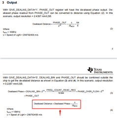
    3. There are also some questions about the two main debugging documents. The calculation formula (4) of "3 Output" in the document "1447.OPT3101-Dealiasing.pdf" is different from the formula (8) of "7.3.8 Output Data" in the document "OPT3101 ToF-Based Long-Range Proximity and Distance Sensor AFE". Of course, this problem is not directly related to the error of the previous register value. Refer to your configuration, no matter which formula is used, the result is wrong.

    My steps are as follows:

    1. Calibrate in HDR mode at 10MHz and save the calibration value in flash area 1.

    2. Calibrate in HDR mode at 8.57MHz and save the calibration value in flash area 2.

    void OPT3101::device::initializeAutoHDR_8P57Hz(void){
    	// List of registers to initialize OPT3101 device after power-up
    
    	this->reg.force_en_slave = 1; // //Since I2C Master bus is floating this register needs to be set to enable device to respond
    
    	this->reg.tg_ovl_window_start = 7000; // //Overload flab observation window
    	this->reg.en_temp_conv = 1; // //Enables the internal
    
    	this->reg.clip_mode_fc = 1; // //Enables Clip mode for Frequency correction
    	this->reg.clip_mode_temp = 0; // //Disables Clip mode for Temp coff phase correction
    	this->reg.clip_mode_offset = 0; // //Disables Clip mode for phase offset correction
    	this->reg.iq_read_data_sel = 3; // //Enables 16 bit frame counter
    	this->reg.iamb_max_sel = 14; // 12=100uA, 14=200uA //Sets maximum ambient support
    	this->reg.gpio1_obuf_en=1; // //Enabled output buffer on GPIO1 pin
    	this->reg.gpo1_mux_sel=2; 	    // //select dig_gpo_0 on gpio1
    	this->reg.dig_gpo_sel0 = 9; 	// //Select Data Ready on dig_gpo_0
        
    	this->reg.num_sub_frames = 8; // //Sub frames count
    	this->reg.num_avg_sub_frames = 8; // //Average frames count
    	this->reg.xtalk_filt_time_const = 4; // //Crosstalk filter time constant
    	this->reg.tg_seq_int_start 	= 9850; // //Sequence Start
    	this->reg.tg_seq_int_end 		= 9858; // //Sequence End
    	this->reg.tg_seq_int_mask_start 	= 8; // //Same as AvgFrame Count
    	this->reg.tg_seq_int_mask_end 	= 8; // //Same as AvgFrame Count
        
        this->reg.illum_dac_h_tx0 = 24;
    	this->reg.illum_scale_h_tx0 = 0;
    
    	this->reg.illum_dac_l_tx0 = 17;
    	this->reg.illum_scale_l_tx0 = 1;
    
        // auto hdr
        this->reg.hdr_thr_high = 10000;
    	this->reg.hdr_thr_low = 800;
    	this->reg.en_adaptive_hdr = 1;
        
    	this->reg.tx_seq_reg   = 2184; // //Setting TX Switching order
    	this->reg.en_tx_switch = 0 ; // //Enable TX Switching order
    
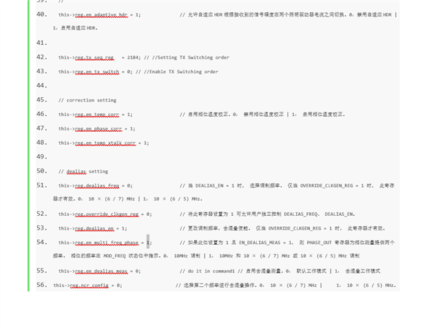
        // 8.57MHz calibration
        this->reg.override_clkgen_reg = 1;
        this->reg.dealias_en = 1;
        this->reg.en_multi_freq_phase = 1;
        this->reg.dealias_freq = 0;                         // 
        this->reg.ncr_config = 0;                           // 0: 10 × (6 / 7) MHz | 1: 10 × (6 / 5) MHz。
        this->reg.sub_vd_clk_cnt = 11665;                   // uint16_t(9999*7/6.0);
        this->reg.tg_illumen_start = 0;                     // uint16_t(0*7/6.0);
        this->reg.tg_illumen_end = 9916;                    // uint16_t(8500*7/6.0);
        this->reg.tg_capture_start = 10850;                 // uint16_t(9300*7/6.0);
        this->reg.tg_capture_end = 11433;                   // uint16_t(9800*7/6.0);
        this->reg.tg_calc_start = 9916;                     // uint16_t(8500*7/6.0);
        this->reg.tg_calc_end = 11665;                      // uint16_t(9999*7/6.0);
        this->reg.capture_clk_cnt = 10033;                  // uint16_t(8600*7/6.0);
        //
        this->reg.en_sequencer = 0;
        this->reg.en_processor_values = 0;
        this->reg.give_dealias_data = 0;
        this->reg.en_dealias_meas = 0;
    
    	this->reg.tg_en = 1;
    
    	this->configurationFlags_xtalkFilterTau =  4; // //This is not a register but a settings flag for the SDK
    	this->configurationFlags_monoshotMode =  false; // //This is not a register but a settings flag for the SDK
    	this->configurationFlags_xtalkSettlingOneTauInMilliSeconds      =  256; // //This is not a register but a settings flag for the SDK
    	this->configurationFlags_xtalkSettlingOneTauInDataReadyCounts   =  16; // //This is not a register but a settings flag for the SDK
    	this->configurationFlags_frameTimeInMilliSeconds                =  16; // //This is not a register but a settings flag for the SDK
    	this->configurationFlags_avgFrameCountExponentOfTwo             =  6; // //This is not a register but a settings flag for the SDK
    }

    3. Calculate alpha0_dealias_scale, beta0_dealias_scale according to internalCrosstalk at 10MHz, and save the calibration value in flash area 3.

    4. Calculate  alpha1_dealias_scale, beta1_dealias_scale according to illumCrosstalk at 10MHz, and save the calibration value in flash area 4.

    5. Get  phase2_offset_hdr0_tx0 and phase2_offset_hdr1_tx0 , and save the calibration value in flash area 5.

    6. Initialize registers of dealias mode.

    void OPT3101::device::initializeDealiasTest(void){
        // List of registers to initialize OPT3101 device after power-up
    
    	this->reg.force_en_slave = 1; // //Since I2C Master bus is floating this register needs to be set to enable device to respond
    
    	this->reg.tg_ovl_window_start = 7000;
    	this->reg.en_temp_conv = 1; // //Enables the internal
    
    	this->reg.clip_mode_fc = 1; // //Enables Clip mode for Frequency correction
    	this->reg.clip_mode_temp = 0; // //Disables Clip mode for Temp coff phase correction
    	this->reg.clip_mode_offset = 0; // //Disables Clip mode for phase offset correction
    	this->reg.iq_read_data_sel = 3; // //Enables 16 bit frame counter
    	this->reg.iamb_max_sel = 14; // 12=100uA, 14=200uA //Sets maximum ambient support
    	this->reg.gpio1_obuf_en = 1; // //Enabled output buffer on GPIO1 pin
    	this->reg.gpo1_mux_sel = 2; 	    // //select dig_gpo_0 on gpio1
    	this->reg.dig_gpo_sel0 = 9; 	// //Select Data Ready on dig_gpo_0
    
    	this->reg.num_sub_frames = 8; // //Sub frames count
    	this->reg.num_avg_sub_frames = 8; // //Average frames count
    	this->reg.xtalk_filt_time_const = 4; // //Crosstalk filter time constant
    	this->reg.tg_seq_int_start 	= 9850; // 以子帧中的 TG 时钟数量 (tCLK) 定义的序列发生器中断 TG 信号的起始位置。
    	this->reg.tg_seq_int_end 		= 9858; // //Sequence End
    	this->reg.tg_seq_int_mask_start 	= 8; // 以帧中的子帧数量定义的序列发生器中断 TG 信号掩码的起始位置。与num_avg_sub_frames一致。
    	this->reg.tg_seq_int_mask_end 	= 8; // //Same as AvgFrame Count
        
    
        this->reg.hdr_thr_high = 10000;
    	this->reg.hdr_thr_low = 800;
        //
    	this->reg.illum_dac_h_tx0 = 24;
    	this->reg.illum_scale_h_tx0 = 0;
        //
    	this->reg.illum_dac_l_tx0 = 17;
    	this->reg.illum_scale_l_tx0 = 1;
        //
        this->reg.en_adaptive_hdr = 1;
    
        this->reg.tx_seq_reg   = 2184; // //Setting TX Switching order
    	this->reg.en_tx_switch = 0; // //Enable TX Switching order
        
        // correction setting
        this->reg.en_temp_corr = 1;
        this->reg.en_phase_corr = 1;
        this->reg.en_temp_xtalk_corr = 1;
    
        // dealias setting
        this->reg.override_clkgen_reg = 1;
        this->reg.dealias_en = 1;
        this->reg.dealias_freq = 0;
        this->reg.en_multi_freq_phase = 1;
        this->reg.en_dealias_meas = 0;
        this->reg.ncr_config = 0;                   // 0: 10 × (6 / 7) MHz | 1: 10 × (6 / 5) MHz。
        this->reg.sub_vd_clk_cnt = 11665;           // uint16_t(9999*7/6.0);
        this->reg.tg_illumen_start = 0;             // uint16_t(0*7/6.0);
        this->reg.tg_illumen_end = 9916;            // uint16_t(8500*7/6.0);
        this->reg.tg_capture_start = 10850;         // uint16_t(9300*7/6.0);
        this->reg.tg_capture_end = 11433;           // uint16_t(9800*7/6.0);
        this->reg.tg_calc_start = 9916;             // uint16_t(8500*7/6.0);
        this->reg.tg_calc_end = 11665;              // uint16_t(9999*7/6.0);
        this->reg.capture_clk_cnt = 10033;          // uint16_t(8600*7/6.0);
    
        // sequencer setting
        this->reg.command0 = 0x100;                 // Set to fo = 10MHz
        this->reg.command1 = 0x102;                 // Set to fo to de-alias frequency
        this->reg.command2 = 0x400;                 // Go to Command0
        //this->reg.give_dealias_data = 1;
        this->reg.give_dealias_data = 0;
        this->reg.en_sequencer = 1;
        this->reg.en_processor_values = 1;
    
    	this->reg.tg_en = 1;
    
    	this->configurationFlags_xtalkFilterTau =  4; // //This is not a register but a settings flag for the SDK
    	this->configurationFlags_monoshotMode =  false; // //This is not a register but a settings flag for the SDK
    	this->configurationFlags_xtalkSettlingOneTauInMilliSeconds      =  256; // //This is not a register but a settings flag for the SDK
    	this->configurationFlags_xtalkSettlingOneTauInDataReadyCounts   =  16; // //This is not a register but a settings flag for the SDK
    	this->configurationFlags_frameTimeInMilliSeconds                =  16; // //This is not a register but a settings flag for the SDK
    	this->configurationFlags_avgFrameCountExponentOfTwo             =  6; // //This is not a register but a settings flag for the SDK
    }

    7. Load calibration parameters at flash area 1 to 5.

    8. In the main loop, read the value of the register at a frequency of 50 Hz and calculate the measured distance.

    // if give_dealias_data = 0
    if (this->data[c1].dealiasFreq == 1) { // 1=8.57MHz
        dist_mm = ((this->data[c1].dealiasBin + this->data[c1].phaseovlf2) * 65536 + this->data[c1].phase) * 0.26688856f; // in mm, PHASE_OUT * (299792458/(2*8570000)/65536*1000) = PHASE_OUT * 0.26688856f
    } else if (this->data[c1].dealiasFreq == 0) { // 0=10MHz
        dist_mm = ((this->data[c1].dealiasBin + this->data[c1].phaseovl) * 65536 + this->data[c1].phase) * 0.22872349f; // in mm, PHASE_OUT * (299792458/(2*10000000)/65536*1000) = PHASE_OUT * 0.22872349f
    }
    
    // if give_dealias_data = 1
    dist_mm = this->data[c1].phase * 2.439717f; // in mm, PHASE_OUT * 299792458 * 64 * 1000 / 65536 / 2 / 10000000 / 6 = PHASE_OUT * 2.439717f

    Best,

    Hertz

  • Hi Hertz,

    Give me some time to look this over. I will reply by the end of this week.

    Thank you,

    Brent Elliott

  • Hi Brent, 

     Any updates?

    Thanks!

  • Hello Reed,

    I will follow up on the email thread.

    Rahland