Other Parts Discussed in Thread: AWR1843,
Hi Team,
Can you please help with the questions below?
- I want to read that information via another software platform with an application that is designed on my own (Matlab, python, C, ...). How can I do that?
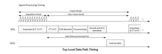
- I have found in the file: Programming Chirp Parameters in TI Radar Devices application.PDF that you mentioned an application ( LRR (225 m as Max unambiguous range)) with its parameters ( see the attachment). It indicates that the total time of acquiring a data frame is approximately 9 ms. My question is: What will be the processing time for one frame of data using the built-in hardware accelerator + DSP on the board?
- If the processing time is more than the time of acquiring the frame of data, will this be considered as not a real-time system?
Thank you kindly.
Regards,
Marvin