This thread has been locked.

If you have a related question, please click the "Ask a related question" button in the top right corner. The newly created question will be automatically linked to this question.

DCA1000EVM: Board abnormal operation

Genius 17595 points
Part Number: DCA1000EVM
Other Parts Discussed in Thread: IWR1843BOOST

Hi Experts,

Seeking your assistance on this query from customer about DCA1000EVM board. Below are their reports.

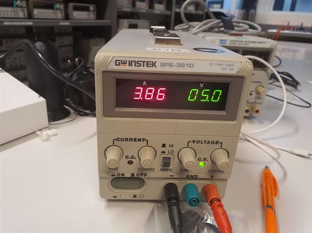
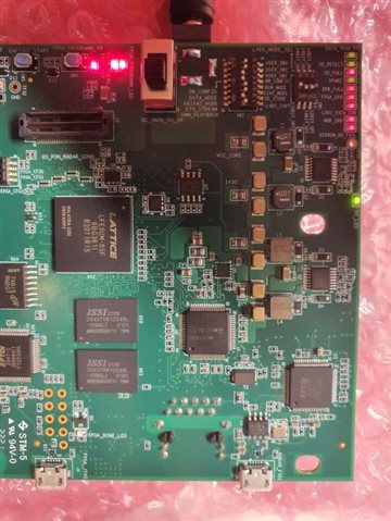
I'm using a DCA1000 EVM, it should be working on 5V-700mA, however once I plug it to a power supply via the jack connector, the power supply shows a drop in voltage, and current needs of about 1.1A - mind you this happens but none of the LEDs on the card light up.

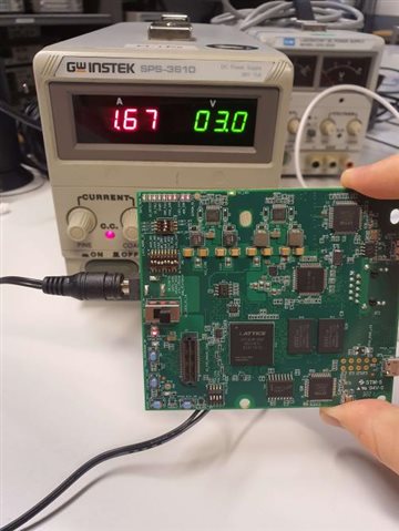
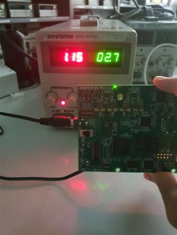
Upping the amps - to around 1.7A, I see the value of 3V on my power supply and at that moment, LEDs do light up- including the "5V-LED".

I'm sorry I don't necessarily know the word for it's those with sort of wheels to adjust the voltage and current ? I'll give you the model exactly so you can better picture what I mean sorry.

***
For your assistance please.
Regards,
Archie A.
Power supply using: SWINSTEK SPS-3610
  • Also, during our initial interaction and from EVM's guide, the board can be powered using 5-V power, either from an external DC adapter, or from TI's xWR1xxx EVM, by selecting the power selection switch (SW3).

    Asked this to the client:
    When you use the DC jack adaptor to power up the device, did you select the SW3 to correct selection (DC_JACK_5V)?

    And below is their response:

    To answer the question, yes. I did check the switch was selecting the correct setup.
    I tried both setups to be frank, even trying to get current from my IWR1843BOOST, we still encountered encountered drops in voltage on our bench power supply- that's also when we realized something else : the current needed to keep both cards powered up would slowly increase,and we realized that the DCA1000 was heating up.

    The heat was mainly on a specific corner of the DCA1000, around the row of LEDs for functional information. We tried looking what components were on this corner, which we think are capacitors and mostly a regulator. We think there is
    either a defect in a component, most likely the regulator in question, or we are using the card in a majorly wrong way.
    Does this mean anything to you?

    For your assistance.

    Regards,
    Archie A.

  • Hello,

    As per user guide on the Radar Toolbox, the recommended power supply is that of a 5V 3A supply. 2.5A can potentially work too but 3A is recommended. Heat generation from the DCA1000 is expected. Without the proper current you can even get to a point where everything seems to be working but when you finally reach the step in which you record raw data, the DCA1000 is unable to record anything and you end up with a blank .bin output file.

    https://dev.ti.com/tirex/explore/node?a=1AslXXD__1.00.00.26&node=A__AGTrhNYW8jE6cMxbovlfaA__radar_toolbox__1AslXXD__1.00.00.26

    Regards,

    Pedrhom

  • Hi Pedrhom,

    Good day. Customer responded:

    Sorry my answers are far between.
    Thank for your answer, the problem is that, to get to 5V, I need to be around 3.95-3.85 A, not 3A... Also, basically all the LEDs possible are lighted up as it is powered up.

    On Table 10, and Figure 18, ALL the LEDs are lighted up, even though there are for instance no SD card inserted, I'm not pressing any FPGA button, no nothing. Speaking of FPGA, there are also LEDs for "FPGA_INI", "FPGA_RST" that are lighted up in red. Again, even sending less current than 5V (for instance 3V, 1.5A) will light up the "5V_LED". To explain further on that point, before plugging the DCA1000, my bench power supply does show 5V, but as I said the voltage drops. This is of course only plugging the DCA1000 and it being plugged to nothing.

    Thank you.

    Regards,
    Archie A.

  • ...Additional information shared:

    So this is when I'm trying to get 5V. At this point in time, the DCA is heating, specifically, the component close to the row of LEDs I told you about, which I read on is a "L24600 YMH", which is a "Wide Input Range Buck Regulator".

    Here are some more info on this :
    - At 3V/1.7A, the LEDs still do light up, but my power supply indicates there isn't enough current for the card (C.C. indicator, photo incoming). No heat, maybe a slight amount.

    - From 2.4A/0.8A to 2.8V/1.4A, only the 5V_LED lights up, which is already concerning on its own. Still having the CC indicator on my power supply (Contrast wasn't really good so I turned off the lights on the picture I took).

    73,
    Archie A.

    Attachments:


    3V-1A67 + all leds + CC.jpg

    2V7-1A15 + 5V_led only + CC.jpg

  • Hello,

    Is there a reason you are not using a standard outlet based 5V/3A power supply with barrel jack connector? For example something similar to this product here 

    https://www.amazon.com/3000mA-Volts-Adapter-Power-Supply/dp/B0852HCM8S

    Best Regards,

    Pedrhom Nafisi

  • Hi Perhom,

    Cx responded:

    Yes, that's because I don't own one for the time being. The lab I'm working has plenty of other adapters that but they don't have the right voltage nor current input, and a bench power supply like the one I'm using should be working just fine.
    Plus, I'm not sure owning one would particularly fix the problem I'm encountering anyway. I'm also positive that the power supply shown in the pics is not at fault, especially taking into account the nature of the issues I'm having.

    Thank you.

    73,
    Archie A.

  • Hello,

    After more details were given offline, I consider this card defective.

    Best Regards,

    Pedrhom