This thread has been locked.

If you have a related question, please click the "Ask a related question" button in the top right corner. The newly created question will be automatically linked to this question.

AWR2243: Boot sequence questions for new design

Part Number: AWR2243


Hello,

we are doing some tests to boot 4 AWR2243P in our own design but unsucessfully for now (radar chips do not send anything on MISO SPI).

(

Question 1 : if QSPI flash is present but with nothing stored in memory, will the AWR2243, I understand that the chip will automatically fall back into the SPI bootmode, is that correct ?

We probed the signals (Master chip) of an automotive radar from which we want to use the host firmware :

Automotive radar 1Automotive radar 2

We see that immediatly after NRESET goes high, SPI INT rises and we can see communications on SPI MISO and MOSI.

Now, here is we measure the signals on an own design :

Own radar 1

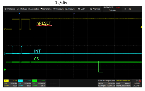
First difference with the automotive reference design : the level of the two first rises is high and not intermediate. We notice that SPI INT goes high for a very short time with the 2 first NRESET rises, but remains low on the third NRESET, which is the "real" start signal of the chip.

Question 2 : What is the condition for the SPI INT to go high when NRESET is pulled up  ?

Question 3 : do you have any advices on what signals we should probe in order to know if AWR2243 chip is correctly going through boot sequence ?

Thanks.

Best regards.


Jeff

  • Hi Jeff,

    I am looking into your questions. Meanwhile, can you clarify the below:

    1. Are you booting the device in functional mode or debug mode?

    2. What is the host interface that you are using and how are you connecting it?

    Regards,

    Swati 

  • Hello Swati,

    1. Functional mode. SOP2 is driven by the host. We will force it to 0 to be sure, I'll get back to you. SOP1 has a 10k pull-down, and SOP0 pull-up to 1,8V.

    2. Host is a FPGA (OpalKelly XEM7360) which is controlled by a PC through a firmware provided by an automotive radar company. I can provide details on our front-end design in private message.

  • Hello Swati,

    SOP2 is driven to 0 just before nRESET is pulled up, but to be sure we're booting in [0 0 1] SPI functional mode, we connected it to GND. We now see  INTR SPI going up nRESET:

     .

    However, we still have nothing coming from the chip on the MISO SPI :

    On the automotive reference design, we see MISO and MOSI signals coming immediatly after nRESET goes up. In our design, we only see MOSI coming from host.

    Does Warm_reset going down and SPI INTR going up implies that the chip correctly boots ?

    Also, we noticed that our nRESET voltage level is 2.5V compared to 1.8V on the reference automotive radar, probably because we didn't put a resistor that they put on this line. Both are in 1.8V VIO mode. Could this lead to the problem we're dealing with ?

    Best regards,

    Jeff

  • Hey Jeff,

    From the picture shared above, it seems that the IOs in your design are not getting the correct power. The signal level of the MOSI line looks to be less than 500mV, which is less than the VIH for 1.8V, hence could be the reason why there is no signal at MISO line.

    Moreover, having the nRESET at 2.5V violates the Absolute Max Rating of the VIOIN_18 mentioned in the AWR2243 datasheet. Yes, it could be a reason for the problem you are facing. I would also recommend checking the other 1.8V pins and ensuring that they are also at the correct levels. 


    Regards,
    Swati

  • Hello Swati,

    we checked the pins. We did some modification to add a few voltage divisors as they did on the reference automotive radar : nRESET, SOP2, RS232 and nERROR_IN. We now have nRESET at 1.8 : 

    nRESET now has the same level as ref design. However, after modification, WARM_RESET doesn't go down anymore after NRESET is up :(

    Also, we can see that OSC_CLOCK_OUT is coming after 645 ms on the automotive radar, which is much more than 7 ms as written in the documentation (but the radar chips are working) , whereas it's always present on our version as soon as nRESET is up. Do you have an idea of what may cause this ? A problem with the XTAL ?

    Moreover, during the verifications we made, we noticed that we didn't connect these 3 output pins : VOUT_14APLL, VOUT_14ASYNTH and VB_GAP. On the reference design, they have decoupling capacitors to GND.Can this cause our problems ?

    I guess we're close to make it work, but there's something we did wrong that we don't see.

    Best regards,

    Jeff

  • Hi Jeff,

    You should connect the decoupling capacitors to GND for these three pins, however, it might not be the reason you are seeing this issue. Have you gone through the Schematic checklist present in the document: https://www.ti.com/lit/zip/sprr407 ? If not, please go through it and check if you have missed anything else.

    Regards,

    Swati

  • Hello Swati,

    We didn't have this checklist. We are checking right now. I'll get back to you when it's done.

    Best regards,

    Jeff

  • Hello Swati,

    we indeed found some issues thanks to the check-list. We are working on a work arround. I will let you know if we succeed the boot once we do the modifications .

    Thank you again for the document.

  • Hey Jeff,

    No problem. Please let me know if you see the issues after the work-arounds.

    Regards,

    Swati

  • Hello Swati,

    thank you again for sharing the checklist. We made a temporary PCB fix to solve the problems we identified with the checklist :

    Now the 4 AWR2243 are booting and according to the logs, we pass MSS PowerUP, MSS BootErrorStatus, RFPowerUp and RfInitialCalibration. RfInitialCalibration returns a different output compared to the reference automotive radar:

    According to ANA#11A from this document, we think TX Power cal and RX IQMM cal fail because the lines are not yet connected to antenna and are not impedance loaded. We will fix that very soon. In the meantime, we tried to change the value of CalibEnMask to bypass Txpowercalib and RXIQMM but this does not seem to have any effect on the following step.

    Unfortunatly, after RfInitCalibration, we receive a error ID 114.

    We understand that Error 114 can be returned by 2 APIs :

    In this forum post the author says "the problem has been solved. The reason for the error is that I did not call rlRfSetMiscConfig before calling rlRfSetPhaseShiftConfig"

    We do have calls to rlSetPhaseShiftConfig in our config file, but no calls to rlRfSetMiscConfig. However, we use the exact same software and config file for the automotive radar and it is working... So I have new question for you (sorry ...) :

    1) Can you confirm that Tx Cal and RXIQMM fails does not have any link with ERROR ID 114 ?

    2) Is there any chance that this error is due to the fact that we are using newer revision of the AWR2243P compared to the automotive reference board ? If so do think we should add a call to rlRfSetMiscConfig in our config ?

    I can share our config file and the detailed logs if that can help.

    Best regards,

    Jeff

  • Hi Swati,

    we'have been investigating this Error ID 114 without any success. We removed the calls to rlRfSetPhaseShiftConfig, but we still have this error 114. I understand that this error can only be returned by either rlRfSetPhaseShiftConfig or rlRfSetMiscConfig but we don't have these API calls in our config file, which doesn't leave us any clue of why we get this error.

    Would you have some advices on what we should investigate ?

    Thanks.

    Best regards.

    Jeff

  • Update : we may have a clue. We looked at the part number of our two radars :

    • Reference automotive : 583 => ES 1.0
    • our new design : 583A => ES 1.1

    So the device firmware loaded at startup is made for ES 1.0 and not ES 1.1. I'll try to get the exact DFP version.

    Do you think that can cause error ID 114 ?

    Best regards.

    Jeff

  • Hey Jeff,

    Yes, the older device firmware can cause the error. Have you been able to try with the new firmware yet?

    Regards,

    Swati

  • Thank you Swati for your answer. We're checking this with our automotive partner.

    In the meantime, we will also look if we can get ES 1.0 chips somewhere, in case we cannot add the new DFP to the firmware. Although I understand they are not sold anymore.

    I'll keep you updated.

    Best regards.

    Jeff

  • Hey Jeff,

    What problems are you facing when you try to use the new DFP? Can you share information about the DFP version?

    Regards,

    Swati

  • Hello Swati,

    I just had an answer from them. It turns out that using the new DFP is not as easy as it seems. They made their firmware, which contains the DFP, for their alpha model of a radar that is now in production with a very different firmware that includes signal processing. The firmware we use (that includes DFP for ES 1.0) was developped 4 years ago and is not maintained anymore. 

    So an easier solution is would be to use ES 1.0 chips for our first prototypes. I have somes ES 1.0 chips that we bought at the beginning of the project, and I'll check with retaillers if it's possible to buy a few more units.

    For the phase 2 prototypes and for production models, we will have our own back-end so we will have the liberty to change the DFP as we want. The decision to use their backend for the phase 1 prototypes was made so we can focus 100% on the front-end design. But as you can see, that is also the cause of problems we must focus on :)

    Anyway, I'll let you know if testing with ES 1.0 resolves the Error ID 114 (I hope so!), so you can close this topic.

    Thank you again for your help, it's very appreciated.

    Best regards.

    Jeff

  • Hello Jeff,

    For your production sensor, it is highly recommended that you use the latest silicon and DFP. There are several critical updates that have been implemented in the latest firmware and silicon. You can refer to the DFP release notes for specific details. For initial prototyping using ES1.0 should be fine, but please do not plan to go to production with this silicon.

    Regards,

    Adrian 

  • Hello Adrian,

    yes that's what's planned ! Using ES 1.0 is just a temporary solution for our first prototypes. We will then switch to ES 1.1 for the following prototypes (which will have our own backend)

    About ES 1.0, is there any way to buy some units somewhere ? We just need  ~20 more units (we only have 10 right now).

    I understand that part number for AWR2243P ES 1.1 is AWR2243ABGABLQ or AWR2243ABGABLRQ1 but I didn't find the part number of ES 1.0. I just know that there were called XAWR2243P and had 583 instead of 583A (ES 1.1) marked on the packaging. Knowing the part number might help us when asking retaillers if they are a few chip left.

    Best regards.

    P.S : I'll get back to you in a few days when we will have tested with ES 1.0 chips.

  • Hello,

    I doubt you would be able to find any ES1.0 available anywhere. The orderable part number is the same for ES1.0 and ES1.1 so there isn't an easy way for the distributor to identify the device revision.

    Regards,

    Adrian  

  • Hello Adrian,

    Indeed, if part number is the same, that won't be easy. I understand there's a lot trace code on the chips. Are there lot trace code groups specific to ES 1.0 ? If yes, is there a way for the retaillers to track these lot trace codes ?

    Best regards.

    Jeff