This thread has been locked.

If you have a related question, please click the "Ask a related question" button in the top right corner. The newly created question will be automatically linked to this question.

DRV5056: Measurement Range and Sensitivities

Part Number: DRV5056
Other Parts Discussed in Thread: DRV5055

Hello, 

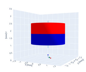
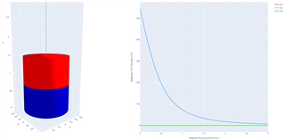
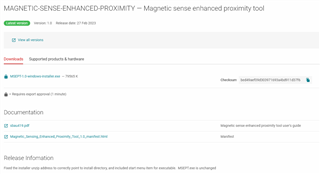
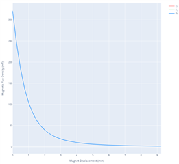
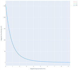
I am a bit confused on how the sensitivities and measurement ranges work for the DRV5056 and the DRV5055. I have 3 different hall-effect sensors (DRV5055 A3, DRV5055 A4, and the DRV5056 A4). I also have a variety of magnets, but I started by using an N35 disc magnet with a radius of 1.25 mm and a thickness of 1.5 mm. I found TI's DRV5056 proximity sensing tool online, have downloaded it, and have been using it as a design tool. This is where I am getting confused with the sensitivities and ranges. 

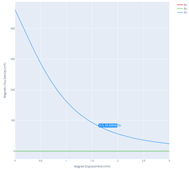
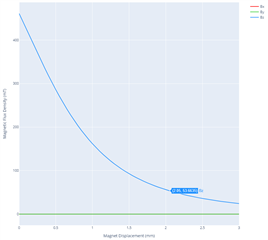
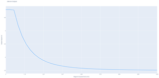
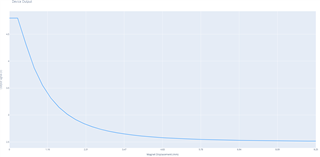
According to this design tool, and other equations that I have found, at 1.6 mm away from the surface of the magnet, the magnetic flux density should be about 83.65 mT. This value is well within the range of the DRV5055 A4 and the DRV5056 A4, and it is at the top of the range for the DRV5055 A3. So, if I am understanding the spec sheets correctly, for the DRV5055 A3, when my magnet is 1.6 mm away, the output from the A3 should be approximately equal to my input voltage of 5 volts, correct? However, this is not the case, at this distance for this sensor and magnet combination, I am reading 3.23 volts. 
 
When using the DRV5056 A4, I find that the output voltages that I measure do not correspond at all to what is predicted by the proximity sensing tool. 
So, I am a bit confused by what voltage values I should be expecting for a given distance. I am also confused on what the sensitivity values mean and how they even factor into my measurements. So, I was hoping someone would be able to help clarify this for me. 
Thank you in advance for any help or information that can be provided. 
- Ross Zameroski 
  • Ross,

    Thanks for reaching out on E2E with your question.  Based on your assessment, it sounds like you have indicated Vcc is 5V and you are getting 3.23V on the output of DRV5055A3 with your magnet at 1.6 mm from the top of the sensor. 

    Since the DRV5055A3 has a sensitivity of 25 mV/mT when Vcc = 5V, we can calculate approximately what input field your sensor might be observing.  Vout is 0.73 V above the quiescent output voltage, and this would suggest about 29.2 mT at the input.

    I first attempted to verify this sounds reasonable by running a quick simulation based on your magnet specs:

    Radius = 1.25 mm, thickness = 1.5 mm, material = N35

    I swept magnet position from 0 mm (i.e. magnet is touching the sensing element within the package) to 3 mm from the sensing element. At a distance to the sensing element of 1.6 mm I would expect 83.65 mT, just like the DRV5056 tool has reported. 

    It is important to remember that this is the distance to the sensing element however, and we should consider the location of the sensor within the package

    With a package thickness of 1.12 mm, this means we should add an additional 0.47 mm to the magnet range.  At 2.07 mm the expected field is now closer to 52 mT.

    Can you confirm that the radius value you provided is not in fact the diameter?  If I re-run this based on a narrower diameter magnet, then the field at 1.6 mm is 28.80 mT, which is more in line with the result you shared

    If DRV5055A3 (25 mV/mT) is being used with an 83 mT input, I would expect to see an increase of 2.09 V from VQ.  This would be about 4.6V out.  Can you also double check that Vcc is 5V? (sensitivity will vary based on actual supply voltage) 

  • Hey Ross,

    Thank you for all the details in your post including variants, that made it much easier for me to check on these. Looks like Scott beat me to it, I'll post my answer anyways in case it additionally helps you. 

    I suspect the differences in output voltages from 5055 vs 5056 can be explained by the Quiescent Offset.  DRV5055 offset is Vcc/2 (which equals 2.5V when powering the device at 5V), and DRV5056 has a constant offset of 0.6V

    I used a prototype tool of ours and agree that for your 1.25mm x 1.5mm axial cylinder N35 magnet the magnetic field should be 83.65mT.  Using that number and the datasheet calculations, I found the expected values:

    • DRV5055 A3 voltage = 2500mV + 83.65mT * (25mV/mT)    = 4.575V at 25­°C.  
    • DRV5055 A4 voltage = 2500mV + 83.65mT * (12.5mV/mT) = 3.538V
    • DRV5056 A4 voltage =  600mV + 83.65mT * (25mV/mT)     = 2.675V 

    I've linked the page in their respective datasheets with the calculation for output voltage which includes sensitivity, offset, and temperature.  Also see the Hall Element Location section of each datasheet - in each sensor (SOT-23 package) the hall sensing element is closer to the center of the package body than the top, resulting in an offset of ~0.3mm from the top of the package.  For the DRV5055 A3 example this added distance would result in a 61.9mT field and 4.03V output instead of the original 83.65mT and 4.58V output. 

    Maybe this combined with other mechanical errors and maybe a slightly weak magnet can explain your 3.23V reading?  The magnet would need to be approximately 2.6mm away from the sensing element to output 3.23V on the DRV5055 A3 if it's a typical N35 magnet at 25°C

    Regards,

    Jacob

  • Scott and Jacob, 

    Thank you both for the quick replies! I can confirm that the input voltage was set at 5 volts and that the radius of the magnet was 1.25 mm. 

    I still have a couple more questions, though. For each sensor, once the measurement range is exceeded, will I get a 5 volt output reading? For example, if the magnet I described above is touching the sensor, the magnetic flux density of the magnet will be higher than the 85 mT measurement range of the sensor and the output will be 5 volts, correct? Will the sensor continue to read 5 volts until the magnet moves to a location where the sensor can read the 85 mT?

    Thank you,

    Ross Zameroski

  • Ross,

    Can you check the marking on the device package for me?

    Also, if the device input is saturated, then the sensor will produce an output close to the 5V supply.  The linear output range of the device is 

    At either end of the range there is a 0.2V margin between the linear response of the sensor and either GND or VCC.  The output will saturate as well, and will not be able to drive all the way to the rail, but the exact voltage is uncertain from the datasheet info.

    Thanks,

    Scott

  • Scott, 

    I don't have the packaging myself. For the moment, I believe that your feedback has resolved my issue. I will reach back out to you if anything changes. 

    Thank you,

    Ross 

  • Scott and Jacob, 

    I apologize, it's been a while since I have looked at this. I am still running into some issues with getting the predicted output voltage to match what I am measuring. 

    I am now looking at data collected with the DRV5055 A4 sensor. I am using the same N35 magnet listed previously (radius of 1.25 mm, thickness of 1.5 mm, and I have been using a Br value of 12,300 Gauss). The sensor is the TO packaging style (all the ones I am using are this style). I start by having the magnet touch the sensor and I am reading 4.836 volts. So, this would correspond to 186.8 mT measured by the sensor. 

    I measured the thickness of the sensor packaging and got 1.54 mm. From the way I have the sensor oriented, I believe that when the magnet is touching the sensor it is approximately 0.51 mm from the sensing element. From the magnetic flux estimation for a disc magnet, at a distance of 0.51mm, I get 289.921 mT. When I substitute this into the Vout equation I get an output voltage of 6.12 V, which would saturate the sensor and output as 5 V, correct? 

    One thing that I noticed on my setup is that I do not have a 0.01 uF capacitor between Vcc and ground, as suggested by the spec sheet. This was something I overlooked when setting up the circuit. Is this something that could potentially be throwing off my results? Or is there something else that I might be missing? 

    Thank you,

    Ross Zameroski

  • Ross,

    For the device package markings, I had intended for you to look at the silk markings that appear on the individual sensor.  I wanted to be sure that you hadn't accidentally installed a different sensitivity than you intended. Are you able to see these markings?

    Our newer magnetics tool which covers more motion and magnet types is now available:

    https://dr-download.ti.com/secure/design-tools-simulation/simulation-tool/MD-8tXHN45LZQ/1.0/MSEPT-1.0-windows-installer.exe

    https://dr-download.ti.com/lit/ug/sbau419/sbau419.pdf

    However, as I showed in the previous response, you should expect to get the same result as the tool you already had for the ideal case.

    I don't think that the 0.01 uF capacitor should cause a problem for sensitivity.  This is a standard decoupling capacitor intended to limit supply noise effects.  

    When testing with the magnet against the face of the sensor, you reported an output of 4.836 V. The linear output range of the device is Vcc - 0.2V, so you are already in saturation.  It is entirely possible to have 289.921 mT at the input, and still only able to measure 4.836 V because of this.  It will be easier to evaluate the sensitivity with the output ranging between 0.2V and 4.8V.

    Thanks,

    Scott

  • I am able to see the markings and I don't believe that I was using the incorrect sensors. 

  • Ross,

    The sensor element in the TO-92 package is roughly placed as shown here:

    and the package thickness is shown here:

    Using the nominal 1.03 mm from the backside of the package we could expect the sensor between 0.39 mm and 0.59 mm from the smaller face of the sensor package (with the silk markings). I have simulated the field from this range (position 0) to 10 mm from the package face using both of these ranges

    0.39 mm

    Magnetic Field

    Sensor Output

    Notice that at close proximity that the sensor is in saturation.  

    0.59 mm

    Magnetic Field

    Sensor Output

    In both cases we see that the sensor is saturated, but as you would expect for the thicker packaging, the magnet is starting .2 mm further from the sensor, and the output profile is shifted by this distance. Based on this result, I would not recommend placing the magnet any closer to the sensor than a 0.5 mm air gap for your test.  

    Can you confirm the range where you see the device come out of saturation?

    Thanks,

    Scott

  • So, for this test, I had the magnet touching the sensor packaging and the output voltage was in saturation (it had an output voltage of 4.836 V). I had the magnet placed on an air bearing stage and commanded a step of 0.050 mm. On the first step, the sensor leaves saturation and has an output voltage of 4.679 V. 

  • Based on the simulations above, we would expect to see 4.679 V somewhere between 0.54mm and 0.34 mm from the surface of the sensor assuming no Sensitivity error.  This shows the sensor is providing output which is near expectation given your magnet specifications.  

    Aside from the package thickness, it is possible that your magnet grade does not exhibit the typical remanence, that the manufacturing tolerances allow for a slight variance in the magnet geometry, or that there is some offset and/or sensitivity error in the sensor.

    Thanks,

    Scott

  • I see. Thank you for all the help!