This thread has been locked.

If you have a related question, please click the "Ask a related question" button in the top right corner. The newly created question will be automatically linked to this question.

TMCS1107: LPF on the output and output load capacitance limit?

Part Number: TMCS1107

Hello,

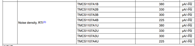
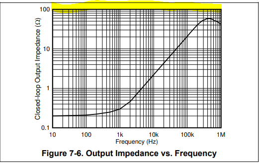
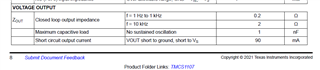
We are using a TMCS1107 to sense a DC motor current and the output of the device is noisy, +/-0.25 A (~100mV) noise on top of actual current measurements.  We have LPF (100ohm and 0.1uF, RC) on the output before it goes into our ADC on the MCU and we still see the +/-0.25 A noise on the measurements.  In the spec for this device there is a 'Max Capacitive load' of 1nF on the Vout pin.  Is our RC causing this noise or is it the expected noise from this device?  To try and reduce this noise we would like to increase the capacitance to decrease the LPF to improve the electrical averaging of the output, would we be violating the Max Load Cap spec in doing so?

Thank you.

  • Mehmet,

    Welcome to the E2E forums! Which variant of the TMCS1107 exactly are you using here? Keep in mind that Hall effect sensors are inherently noisy devices, and I would actually expect that your noise is a bit worse than what you are seeing. For the RC filter you are currently using, the cutoff would move the BW of the output down to 1/2*pi*RC = 15.915kHz. Here are the noise density values from the TMCS1107 datasheet:

    Using the A3B variant as an example (I assumed 200mV sensitivity based on the Amps to Voltage numbers you provided), and analyzing the noise density via a brick wall approach, this would show that the expected RMS output referred noise is 225E-6 x sqrt(15915) = 28.38mVrms, and extrapolating this to a 6-sigma peak to peak makes this potentially 170mVpp. 

    That being said, your proposed approach should help pull this in if you continue to reduce the device BW. For most amplifiers, when a capacitive loading is given in the datasheet, it is discussing the direct node's ability to drive capacitance, as the capacitance will interact with the output impedance of the amplifier and erode phase margin until the amplifier output becomes unstable. Isolation resistance such as the 100Ω you have introduced here helps "alter" the output impedance of the amplifier such that the combined impedance curve is stable. For the 100Ω's you are using, you can see that this should alter the output impedance of the amplifier to a point where practically any value of capacitance present should be fine, and the expected output should be roughly that of a standard 1st order response.

  • Carolus, 

    Thank you for the response.

    We are using the TMCS11073A device.  We are trying to measure motor currents in the ~0.5A fairly accurately and finding this is not a great solution for that because of the noise.  Would you recommend another device to more accurately measure in this range but still have headroom up to ~4-5A?

    I will be modify in the RC now that I understand that it should not be a problem for the output max cap and see if averaging it out with an stronger RC will help.