Because of the Thanksgiving holiday in the U.S., TI E2E™ design support forum responses may be delayed from November 25 through December 2. Thank you for your patience.

This thread has been locked.

If you have a related question, please click the "Ask a related question" button in the top right corner. The newly created question will be automatically linked to this question.

MMWCAS-DSP-EVM: How do I sync timestamp of captured data with external source with microseconds accuracy

Part Number: MMWCAS-DSP-EVM
Other Parts Discussed in Thread: LMK00804B, MMWCAS-RF-EVM

Here is what I need to achieve:

1. I recently bought the board for developing radar application. I will have an external sensor capture data at the same time as the MMWCAS-DSP-EVM, both of them needs to be time-stamped as it captures. So later in the postprocessing I'll be able to match the timestamp and process them together.

2. If they are captured with different starting time, the difference in start-to-capture time needs to be known, so that I could align them in post-processing. 

Here is the information I gathered so far:

1. The MMWCAS-DSP/RF-EVM doesn't have a PPS input ping, so I cannot do time-sync with PPS and GPGGA

2. DSP EVM support PTP sync via kernel driver. Which in theory can achieve microsecond accuracy. Here is the post where it found this information. 

Here is my question:

1. I checked the _idx.bin data generated after the capture, but it seems in timeStamp data it starts from the time you started your radar device. After I managed to do ptp sync, is there anyway to know the difference between this timeStamp data and onboard linux system time? Or maybe I could ask it to use onboard linux system time instead?

    Here I attached the result of reading idx.bin from matlab:
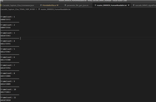
2. Just in-case PTP is a dead end, is there any workaround for what I'm trying to achieve? 

Thank you in advanced!

  • Hi,

    Let me understand your question correctly. You have 2 radar devices whose data you would like to align in time for post processing. One of them is a (MMWCAS_DSP_EVM + RF_EVM) and the other is an external one?

     If so, there is a provision of using SYNC_IN/SYNC_OUT pins which are digital I/O pins that are used to synchronize the framing of the cascaded devices. You can provide this SYNC_IN signal from an external host which would control both your radar devices. You can also use the SYNC_OUT pin's signal to identify exactly when the framing started. You can read more about this here AWR2243 Cascade (Rev. B) (ti.com) -> Section 5.3

    Please let me know if this is what you were looking for.

    Regards,

    Kaushik

  • Hi Kaushik Gowda. 
    Thank you for the reply. 

    I have 1 MMWCAS EVM set (1 DSP 1 RF board), and I have a external IMU sensor. 

    Regarding the pins you mentions, I don't think I can use them to synchronize if I'm using EVM board right? As they are not exposed physically I believe.

    Please correct me if I'm wrong

    Thank you

    Yichen Li

  • Hi Yichen,

    You are right. There is no direct pin provision but the same lines flow through the LMK00804B buffer (Figure 3 of MMWCAS-RF-EVM User Guide). You will have to make a few changes on the EVM to accommodate this. Can you let me know which EVM revision it is that you are using? I will also check to see if any other method can be adopted accordingly.

    Regards,

    Kaushik

  • Hi Yichen,

    The method mentioned above is going to be very intrusive and is not recommended. Let me see if there is a simpler choice of just getting trigger timestamps.

    Regards,

    Kaushik

  • Surething, The version we are using is

    RF EVM: Rev-D

    DSP EVM: I couldn't found the revision number on the board. 

    Thanks for the mention, yes I found it on the page you mentioned:  LMK00804B (U8) AWRx digital synchronization distribution buffer. 

    When you said making a few changes, did you meant by hardware? or software. 

    Thank you

    Regards

  • just saw this message, I guess you meant hardware changes then :). Also I wonder what's your opinion regarding my proposal of PTP? Thanks!

  • Hi Kaushik, any luck yet? Slight smile

  • Hi,

    I have the following questions:

    • Will you be performing a ptp sync for triggering of every frame?
    • Ideally this trigger would be sending an SPI message to the RF RVM based on the CPSW timer? The delay taken by SPI can be calculated by taking local timestamps on the TDA device. So, you can add this additional offset in your post processing. 
    • If not, can you please explain your current trigger mechanism of the RF EVM using PTP?

    Regards,

    Kaushik

  • Hi Kaushik

    Thanks for the reply. 
    Replying to your questions.

    Regarding Question (3), we currently do not have a way to trigger the capture apart from using mmWave Studio, ptp is our proposal. 
    Regarding Question (2) and (1), Where is the SPI message send from? We only have ti's RF and DSP EVM board at the moment. So I suppose the SPI message is send from the external PC to the DFP on DSP board right?

    In summary I have the following new questions:
    1. There's a linux system running on DSP EVM board, when you said "the delay taken by SPI can be calculated by taking local timestamp on TDA", but I thought the time on linux system is running on miliseconds accuracy and thus we are not able to get a microseconds accuracy in terms of the delay right?
    Unless we use rtos instead. But if we switched to rtos, is TI's DFP support rtos system?, How about mmWaveStudio, does mmWaveStudio support RTOS?

    2. From what I understand so far, the current proposal is, use PTP or Soft interrupt to trigger Radar SDK running on the DSP board to make a capture, radar SDK will request DFP to make a capture.  Suppose that its running on RTOS (Radar SDK supports RTOS), we then store the timestamp according to the RTOS/Trigger time. Save that for later post processing. Please correct me if I'm wrong. 


    Looking forward for your reply. 

    Thank you. 

    Yichen Li

  • Hi Yichen,

    Where is the SPI message send from? We only have ti's RF and DSP EVM board at the moment. So I suppose the SPI message is send from the external PC to the DFP on DSP board right?

    SPI is used to send messages back and forth between the RF EVM and the DSP EVM. Think of the DFP as an application that runs on the radar device that is capable of this message communication (feedback and reporting) and data out. The DSP EVM would be running an application that sends messages such as configuration, software trigger etc. You can refer to the ICD document which is part of the DFP to understand what these messages look like.

    What I referred to earlier was that this software trigger would have known latencies that can be calculated. (Soft trigger -> Frame start -> Frame end async event, therefore soft trigger approx. latency = total framing time - timestamp of the frame end async event).

    But if we switched to rtos, is TI's DFP support rtos system?, How about mmWaveStudio, does mmWaveStudio support RTOS? -> The DFP is blind to the OS that the commanding application is running on and only sees the SPI messages as mentioned earlier. Regarding the application running on the DSP EVM in a linux environment, I will check with the team as to what can be done to obtain more timing precision.

    Regarding your question 2, there is one more suggestion I have. There is a demo usecase part of the Processor Radar SDK 3.8 called cascade_radar_capture_only which basically captures the ADC data and streams the same out via ethernet. You can also use this tool to perform data capture and have control over the trigger. Let me know if you can use this.

    Regards,

    Kaushik

  • Hi Kaushik
    Thank you for the reply

    [SPI topic]

    So I suppose currently there's two way DFP is controlled,

    1. mmWaveStudio(On pc) -> mmWaveLink (On Pc) -> mmWave firmware (On DSP) -> SPI commands for controlling the radar devices. 

    2. Processor Radar SDK (On DSP) can control the mmWave firmware (On DSP) directly to make capture. 

    Please correct me if I'm wrong.

    [Software trigger topic]

    I will check processor SDK to see how to implement it. thank you. 

    [RTOS topic]

    1. When you said blind to the OS, I suppoose you meant it doesn't matter if its rtos that's running or linux right? So I can use RTOS all fine?

    2. Thank you, looking forward for your response. 

    [Processor Radar SDK sugguestion]

    I found the demo you mentioned in ProcessorSDKRadar_UserGuide, topic 3.9.1. Thank you, I will take a look and post my findings here. 

  • Hi Yichen,

    • Your understanding on the SPI topic is correct.
    • Please go ahead and try using RTOS and let me know how it goes.
    • The demo in 3.9.1 is for a single radar device configuration using the TDA3x. You should be looking at the cascade usecase.

    Regards,

    Kaushik

  • Hi Kaushik

    Thanks for the reply. I succesfully run the demo on the board. Here is a screenshot of it, seems like I'm on the right track?


    Regarding RTOS, in the demo provided, it seems to be printing timestamp like 18400.870493s, so likely its going to be (Microseconds) accurate enough for our usecase. As long as we could know the exact delay that happens, we can offset it in later postprocessing. 

    Thank you! I think my issue is solved. 

    Best 

    Yichen Li