This thread has been locked.

If you have a related question, please click the "Ask a related question" button in the top right corner. The newly created question will be automatically linked to this question.

LMP91000: Configuration with external sensor

Genius 17525 points
Part Number: LMP91000

Hi Experts,

Seeking your assistance please.

Customer has a two -electrode alcohol sensor dart, wanted to connect it to the LMP91000 potentiostat.

As stated in the documentation, it can be connected in 3-LEAD mode, for this you also need to scrape Reference Electrode and Control Electrode. I attach to the working electrode to a +, and minus to the reference and control as in Datasheet.

Programmatically, they can change the parameters of op_mode, bias, ref_source, and so on, what values need to be selected for each mode? For example, what amplification or cooperation we need? What internal support voltage? Or is it better to connect this type of sensors in 2-LEAD GALVANIC CELL?

For your assistance.

73,
Archie A.

16mm_breath_alcohol_sensor_product_datasheet.pdf

  • Archie,

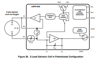
    The customer will operate this sensor in a 2-lead galvanic cell in potentiostat configuration.

    This sensor is not in our data base. All this means is that they will have to figure out what settings will be needed. I can help, but I cant tell them exactly what they should be. 

    The LMP91000 is a transimpedance amplifier. That means that the sensor will develop a current based on gas concentration. The TIA in the LMP91000 will provide a voltage based on gas concentration. RLoad is basically a current shunt. The TIA will measure the current across the shunt as a voltage. The conversion from current to voltage is based on the gain

    2-Lead Galvanic Cell = Gain= 1+(RTIA/RLoad) 

    The transimpedance amplifier uses an op-amp and a feedback resistor to generate an output voltage that is proportional to an input current.
    The magnitude of the gain is equal to the feedback resistance, and since inversion occurs, the circuit’s transfer function is VOUT= −Iin×Rf
    Like a resistor, a transimpedance amplifier converts current to voltage, but unlike a resistor, it has low input impedance and low output impedance even with very high gain.
    A compensation capacitor connected in parallel with the feedback resistor is used to ensure stability in sensor applications.

    If you know what current you should have at a specific level based on the sensor then you can calculate the current across the RLoad then determine the gain that you need to get a voltage that is acceptable for your ADC.

    Remember the temperature will impact every measurement. Use the measured temperature at the voltage you measure based on the standard to develop a temperature correction algorithm. 

    Since this circuit will operate on a single rail supply, you will need to add a voltage offset to be used as a zero. The measured gas concentration will be relative to the zero.

    Let me know if the customer wants a quick call and I can explain in more detail. It is more simple than it first looks. Break it down into separate circuits and understand how they work.

    I will close this for now. Let me know if the customer wants a meeting.