Other Parts Discussed in Thread: IWR6843
Hi Team,
I didn't find the code for parsing the bin file of AWR6843OPEVM in the second document https://www.ti.com/lit/an/swra581b/swra581b.pdf in your reply. Does the document not contain such code or is this code similar to those for others? Which code should I refer to? And what is the data format of this radar version?
Also, is the number of LVDS lanes mentioned in this document different for different versions of the radar? Is my version of AWR6843AOPEVM (F) fixed with 2 lanes? So does it mean that the radar with at most two lanes can only turn on at most two receivers at the same time? That is, does one lane accept the signal received by one receiver?
To put it another way, what can the number of lanes determine? Does it mean being able to transmit at the same time? That is, does a channel only accept one value at a time? But does having two mean being able to accept two values at the same time? But according to the document, if there are two lanes, we cannot use 3 receivers. I'm a little confused about this. The original text in the document goes like
Because only two LVDS lanes are used, data capture using 3 receivers is not available with the xWR16xx/IWR6843.
Besides, what is the difference between the IQ of the receiver? Is one a real number and the other an imaginary number? Then when I use the data later, do I need to combine real and imaginary numbers together? But I notice that the data I collected are actually in plural form, and there will be a row of Chirp data with values and row of Chirp data without values. Then the amount of data is still twice the value set. It's shown below.
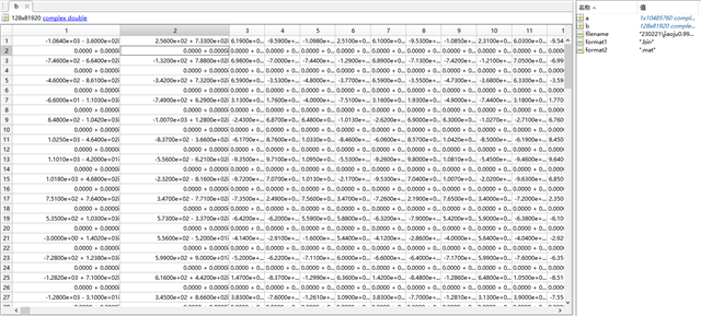
I am using the Complex 1x mode. The ADC sample is 256, the No of chirp loops is 128, and the No of frame is 160. Thus, the calculation should involve the 5,242,880 complex values, right? If the IQ is separated, it will be doubled. But there is no separation here except for the fact that one row is vacant.
Could you tell me the reason for this?
The code for parsing the bin file I used is also attached here. Could you please help me check if there is any error? Thank you.
%%% This script is used to read the binary file produced by the DCA1000
%%% and Mmwave Studio
%%% Command to run in Matlab GUI -readDCA1000('<ADC capture bin file>')
function [retVal] = readDCA1000(fileName)
%% global variables
% change based on sensor config
numADCSamples = 256; % number of ADC samples per chirp
numADCBits = 16; % number of ADC bits per sample
numRX = 1; % number of receivers
numLanes = 2; % do not change. number of lanes is always 2
isReal = 0; % set to 1 if real only data, 0 if complex data0
%% read file
% read .bin file
fid = fopen(fileName, 'r');
adcData = fread(fid, 'int16');
% if 12 or 14 bits ADC per sample compensate for sign extension
if numADCBits ~= 16
    l_max = 2^(numADCBits-1)-1;
    adcData(adcData > l_max) = adcData(adcData > l_max) - 2^numADCBits;
end
fclose(fid);
fileSize = size(adcData, 1);
% real data reshape, filesize = numADCSamples*numChirps
if isReal
    numChirps = fileSize/numADCSamples/numRX;
    LVDS = zeros(1, fileSize);
    %create column for each chirp
    LVDS = reshape(adcData, numADCSamples*numRX, numChirps);
    %each row is data from one chirp
    LVDS = LVDS.';
else
    % for complex data
    % filesize = 2 * numADCSamples*numChirps
    numChirps = fileSize/2/numADCSamples/numRX;
    LVDS = zeros(1, fileSize/2);
    %combine real and imaginary part into complex data
    %read in file: 2I is followed by 2Q
    counter = 1;
    for i=1:4:fileSize-1
        LVDS(1,counter) = adcData(i) + sqrt(-1)*adcData(i+2); LVDS(1,counter+1) = adcData(i+1)+sqrt(-1)*adcData(i+3); counter = counter + 2;
    end
    % create column for each chirp
    LVDS = reshape(LVDS, numADCSamples*numRX, numChirps);
    %each row is data from one chirp
    LVDS = LVDS.';
end
%organize data per RX
adcData = zeros(numRX,numChirps*numADCSamples);
for row = 1:numRX
    for i = 1: numChirps
        adcData(row, (i-1)*numADCSamples+1:i*numADCSamples) = LVDS(i, (row - 1)*numADCSamples+1:row*numADCSamples);
    end
end
% return receiver data
retVal = adcData;
Kind regards,
Katherine