This thread has been locked.

If you have a related question, please click the "Ask a related question" button in the top right corner. The newly created question will be automatically linked to this question.

TMAG5273: Issue with CRC Calculation

Part Number: TMAG5273
Other Parts Discussed in Thread: TMAG5173-Q1

We are using the TMAG5273 sensor. We would like to use the CRC feature (CRC_EN=1), and we follow the arithmetic given in section 7.5.1.3.6 of the datasheet (SLYS045A) to validate the checksum.

The checksum appears correct the first time around only; for subsequent reads, we are unable to validate the checksum.

For example:

  1. The first time, we receive 0x00 0x09 0x00 0x18 0x00 0x2B 0xB1 0x52, where the last byte is the CRC. Following the algorithm to compute the checksum over the command byte (0x6B) and first seven bytes gives us the expected result 0x52.
  2. The second time, we receive 0x00 0x13 0x00 0x13 0x00 0x2F 0x91 0xDA. Using the same algorithm gives a CRC of 0xEF, which does not match the transmitted value of 0xDA.
  3. The third time, we receive 0x00 0x0D 0x00 0x19 0x00 0x2A 0x31 0x49, where again the CRC does not match.

Is there anything that we might have overlooked?

  • Frank,

    Thank you for reaching out on E2E. The equations shown in section 7.5.1.3.6 apply to only a single byte of data being read.  Can you confirm you are applying the CRC calculation on the entire 4 byte read?

    Thanks,

    Scott

  • Hello Frank,

    We also have the code examples for TMAG5273 which contain how to calculate the CRC, you can confirm if this is the way it was implemented in your function or use the code in your micro.

    Here is the download link: https://dr-download.ti.com/secure/software-development/firmware/MD-eOz9dMgxSG/1.0.0/TMAG5x73-EXAMPLE-CODE.zip

    Best,

    Isaac

  • Scott,

    yes, I can confirm that we are applying this algorithm to all bytes that we believe should be covered by the checksum. Our C implementation is also getting the same results as the Python crc module that we are using for comparison. And we consistently get a correct result for the first measurement that we receive after power-on.

  • Isaac,

    thank you for that link, however, it does not work for me. I am getting a timeout error trying to access it. I will keep trying later today. Is there any chance of providing a different link or pasting the code here?

    Thanks,

    Frank

  • Frank,

    Please refer to the example calculation here:

    uint8_t TMAG5x73calculateCRC(uint8_t i2cRead, uint8_t numChannels, uint8_t data[])
    {
        if ((i2cRead > 0x02) || (numChannels == 0) || (numChannels > 0x04)) assert(1 == 0);
    
        int i = 0;
        uint8_t crc = 0xFF;
        uint8_t crcNew = 0x00;
        uint8_t d[8];
        uint8_t c[8];
        int j = 0;
    
        if (i2cRead == 0x01)
            numChannels = numChannels * 2;
        else if (i2cRead == 0x00)
            numChannels = 4;
    
        for (i = 0; i < numChannels; i++)
        {
            for (j = 0; j < 8; j++)
            {
                d[j] = (data[i] >> j) & 0x01;
                c[j] = (crc >> j) & 0x01;
            }
    
            crcNew = d[7] ^ d[6] ^ d[0] ^ c[0] ^ c[6] ^ c[7];
            crcNew |= (d[6] ^ d[1] ^ d[0] ^ c[0] ^ c[1] ^ c[6]) << 1;
            crcNew |= (d[6] ^ d[2] ^ d[1] ^ d[0] ^ c[0] ^ c[1] ^ c[2] ^ c[6]) << 2;
            crcNew |= (d[7] ^ d[3] ^ d[2] ^ d[1] ^ c[1] ^ c[2] ^ c[3] ^ c[7]) << 3;
            crcNew |= (d[4] ^ d[3] ^ d[2] ^ c[2] ^ c[3] ^ c[4]) << 4;
            crcNew |= (d[5] ^ d[4] ^ d[3] ^ c[3] ^ c[4] ^ c[5]) << 5;
            crcNew |= (d[6] ^ d[5] ^ d[4] ^ c[4] ^ c[5] ^ c[6]) << 6;
            crcNew |= (d[7] ^ d[6] ^ d[5] ^ c[5] ^ c[6] ^ c[7]) << 7;
    
            crc = crcNew;
    
        }
    
        return crc;
    }

    Thanks,

    Scott

  • Scott, thank you for posting the code. I was able to compile the code into a test program. However, I was not able to validate our received CRCs with that code.

    Our CRC implementation produces the same results as this code, given the same input bytes. So I guess the question is which of the received bytes should be included in the checksum calculation.

    We are using the 1-byte I2C read command for three channels (XYZ) of 16-Bit data with CRC enabled, as in the third sub-figure of figure 7-12. I thus receive 8 bytes from the sensor: 6 channel data bytes, 1 byte of data[CONV_STATUS], and one byte of CRC. These are the bytes that I quoted in my initial post above.

    Now, the above code, given these inputs, only computes a checksum over the 6 channel data bytes, because the loop will run from 0 to 3*2. However, using this logic, I am still unable to validate the results that I am seeing.

    Thank you,

    Frank

  • Frank,

    I want to be sure I'm calculating CRC correctly based on the data you provided.  Can you send the starting register value?  That is:

    0x6A, 0x??, 0x6B ... Data

    Thanks,

    Scott

  • Scott,

    I am using 0x6B as the initial byte for the CRC checksum. For the three examples from my initial post:

    1. CRC(0x6B, 0x00, 0x09, 0x00, 0x18, 0x00, 0x2B, 0xB1) = 0x52, which matches the received CRC byte.
    2. CRC(0x6B, 0x00, 0x13, 0x00, 0x13, 0x00, 0x2F, 0x91) = 0xEF, which does not match the received CRC byte, which is 0xDA.
    3. CRC(0x6B, 0x00, 0x0D, 0x00, 0x19, 0x00, 0x2A, 0x31) = 0x7C, which does not match the received CRC byte, which is 0x49.

    Thanks,

    Frank

  • Frank,

    Have you set the I2C_RD setting to 01b?  If attempting to read this many registers in standard 3-Byte mode, then CRC is not supported for reads greater than 4 bytes:

    Thanks,

    Scott

  • Scott,

    yes, I2C_RD is set to 1.

    Our sensor configuration is:

    • DEVICE_CONFIG_1 reigster:
      • CRC_EN = 1
      • CONV_AVG = 5
      • I2C_RD = 1
    • DEVICE_CONFIG_2 register:
      • OPERATING_MODE = 2
    • SENSOR_CONFIG_1 register:
      • MAG_CH_EN = 7

    All other registers are left at their reset value.

    Thanks,

    Frank

  • Frank,

    Thank you for confirming.  I get the same CRC calculated values when I process the data you provided. Can you confirm the clock rate and timing between start and stop commands?  If possible, it would help if you could capture a scope screen shot of the I2C transactions.

    Thanks,

    Scott

  • Scott,

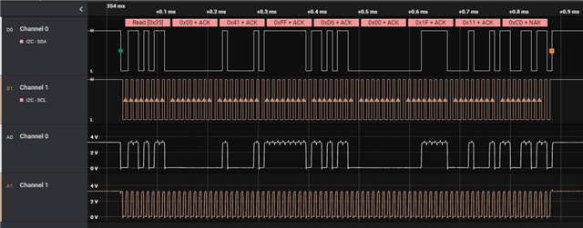
    here is a frame grab from a logic analyzer. The I2C is configured to the standard 100 kHz. We are using an ST microcontroller's built-in I2C peripheral, so timing really should not be an issue.

    Frank

  • Frank,

    I've been working to communicate this issue with the design team and have confirmed that there is an errata in the data sheet.  To use CRC with this device, it needs to be in the full 3 byte read mode and must capture no more than 4 consecutive data bytes as indicated in the note I pointed to above.  I do apologize for the inconvenience this causes.  The data sheet will be updated to reflect this.  

    If this read mode is required, TMAG5173-Q1 operates with CRC in the 1 byte read mode for both 8 and 16 bit read modes.

    Thank you for your patience in all of this.

    Scott

  • Scott,

    thank you for your response. This does not exactly resolve the issue, but certainly explains it. When will the errata sheet be published? Can I get an advance copy for our records?

    Do I understand you correctly that this issue will be fixed in an updated revision of this device? I can not find other references to "TMAG5173-Q1" elsewhere. When will this revision be available?

    Frank

  • Frank,

    TMAG5173-Q1 is a different device which operates with similar base functionality to TMAG5273:

    https://www.ti.com/product/TMAG5173-Q1

    I do not know that TMAG5273 will receive any silicon changes to increase the CRC coverage to match TMAG5173-Q1. 

    The datasheet author has not yet been able to begin drafting the changes to the document, and is working to scope out the timeline on it still, but this update will be made.

    Thank you,

    Scott

  • Ah, I see. Thank you for the clarification.