Other Parts Discussed in Thread: TIDEP-0091,
Hello,
I'm studying the TIDEP-0091 Design Guide. On point 2.2, we can read the following:
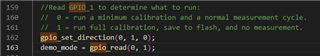
"GPIO-1 MSP432 output to the mmWave sensor input for mode control, 1=Calibration, 0 = Functional cycle"
Then, on point 2.6, on Figure 7: TIDEP-0091 Level Sensing Control and Communication Sequence, we can see the following:
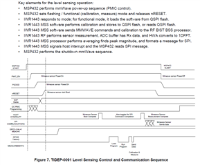
We can see on the description of the operation on the top, that after responding to mode, the IWR1443 performs calibration. What we can observe in the signals diagram is that there's an interval after "MMwave sensor start Boot" and then GPIO-1 changes its state from 0 to 1 (from the text, we can interpretate that's the period at which the MSS software is performing the calibration).
But according from the first definition, shouldn't it be the opposite? I thought that pin state would be changing from 1 to 0 after calibration is complete, but maybe I'm not fully understanding the pin functioning.
I've been looking at IWR1443 Datasheet and there is no specification that GPIO1 is an active low signal.
I want to know to be sure to know how to implement these signals from the MCU.
Best regards,
Julia S.