This thread has been locked.

If you have a related question, please click the "Ask a related question" button in the top right corner. The newly created question will be automatically linked to this question.

DRV5013: Hall Latches and Hall Switches

Part Number: DRV5013
Other Parts Discussed in Thread: TMAG5115, TMAG5115EVM

We are designing position sensing circuit for BLDC Motor (Control strategy is Six step commutation), where we are planning to use DRV5013 Hall latch. We are having few queries on that,


  1. Why magnetic switchs cannot be used instead of the Latches for this Motor control application ? Can you please send any reference design/ application note explaining the use of magnetic switch in Motor control application instead of Latch, if there is any ?.
  2. In DRV5013, apart from the pull up resistor, is it necessary to connect the Capacitor (C2 as per datasheet) if we are already having a single pole first order RC filter deployed on the line ? What purpose do the capacitor C2 serve apart from filtering ?
  3. What should be the cut off frequency of that RC filter (question-2),as recommended by TI if the required bandwidth of the sensor is 4500Hz ? On What basis the filter cut off frequency is decided ?
  4. Why this DRV5013, is rated with higher voltage, upto 38V ? For what application it is rated with this high voltage ? For those application, is it recommended to directly bias this with, say 30V ? What are the benefits seen here?
  • Hello Sweshwaran, 

    Thanks you for posting to the sensing forum! Just as a preface we have also released a new device the TMAG5115, the device was with BLDC motor applications. It offers a higher bandwidth, less delay, and jitter than the DRV5013 for more precise switching.

     To answer your questions:

    • Why magnetic switches cannot be used instead of the Latches for this Motor control application ? Can you please send any reference design/ application note explaining the use of magnetic switch in Motor control application instead of Latch, if there is any ?
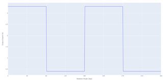
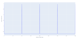
      • Unfortunately we do not have the document you are requesting but I can explain why you would not want to do this. The hysteresis is set up differently for Hall switches vs latches. Hall switches will change output as soon as the field drops below the release point, while latches will change output until the polarity of the magnet changes. You may be able to use unipolar switches (switches that are only sensitive to one polarity) but it would be very sensitive to placement. Placements would need to guarantee a 50% duty cycle of hall effect sensor transitions during a rotation. A Hall latch essentially guarantees a natural 50% duty cycle between poles and is not as sensitive to placement. It is not possible to use an omnipolar switch since they are sensitive to both north and south fields. Please look at the output images below: 

                         First image is the output of a latch, while the second image is the output of an  omnipolar switch for the same rotor.


    • In DRV5013, apart from the pull up resistor, is it necessary to connect the Capacitor (C2 as per datasheet) if we are already having a single pole first order RC filter deployed on the line ? What purpose do the capacitor C2 serve apart from filtering ?
      • The C2 capacitor is not required. This is an optional component as noted in the datasheet most applications do not require the C2 filtering capacitor. There is no other purpose for the capacitor other than the filter provided.
    • What should be the cut off frequency of that RC filter (question-2),as recommended by TI if the required bandwidth of the sensor is 4500Hz ? On What basis the filter cut off frequency is decided ?
      • If a filter is required, it is recommended to provide at least two times the bandwidth required for your system. In your case this would mean that the filter cutoff should be max 9000Hz but ideally you would want to give your system 3 times the bandwidth required, so the cutoff should be around 13.5kHz. Keep in mind most systems do not require the filter so you may not need to limit the sensors bandwidth.
    • Why this DRV5013, is rated with higher voltage, up to 38V ? For what application it is rated with this high voltage ? For those application, is it recommended to directly bias this with, say 30V ? What are the benefits seen here?
      • There are a couple of reasons why the DRV5013 is rated up to 38V mainly done for designers flexibility, but changing the voltage does not offer any benefits compared to 3.3V. In a BLDC application the main reason for such a high voltage is due some systems have the motor and the device connected to the same bus. When the motor spins to a stop it generates a voltage on the bus that exceeds the normal bus voltage. Adding bulk capacitors here helps or having the system break instead of spin to a halt limits this voltage but if no protection is added here the device is able to protect itself. In some other instances some users will have a 12V bus or 24V bus but don't want to get an extra regulator, that is not an issue since the DRV5013 can work on that voltage as well. 

    Here is some other literature that might help: https://www.ti.com/lit/an/slvaeg3b/slvaeg3b.pdf

    The TMAG5115EVM is compatible with NEMA17 BLDC motors so it can be used as a module to place for trap commutation: https://www.ti.com/tool/TMAG5115EVM

    I hope this helps!

    Best,

    Isaac

  • Hi Lara, Is there any through hole variant of TMAG sensors available, equivalent to DRV5013?

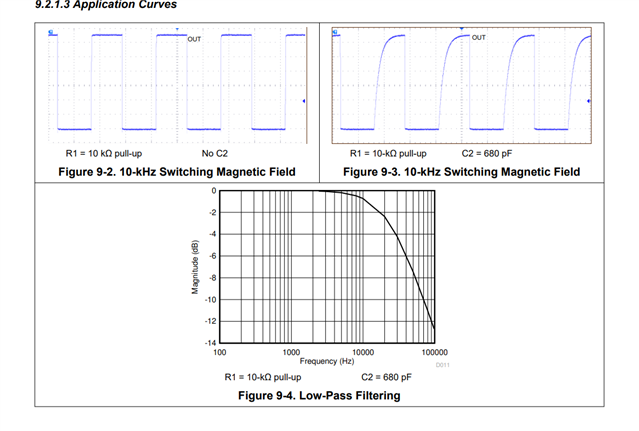
  • Also, If the C2 capacitors are not functionally required. then why in Datasheet C2 is calculated, with a cut off frequency of 10kHz, as this definitely creates slow edges (rise time is considerable) on the filter output?

  • Hello Sweshwaran,

    As Isaac is out the rest of this week, I will try to answer your questions.  As of now, we do not have a TMAG device available in a through hole package.  As for the application example  found in the datasheet, it serves as a reference for someone who may want to filter the output.  I agree, there is not a adequate justification provided for why someone would want to do that.  Perhaps it could be used for implementing some dead time between two different Hall latch outputs crossing thresholds.  The author did not specify and I assume it that is was motivated by some prior customer inquiry.  However, in Figure 8-1, the datasheet does mention that C2 is optional.  Therefore, if you want a maximally fast output response, you do not need to use C2.